CAMSHAFT OIL CONTROL VALVE INSTALLATION

-
INSTALL CAMSHAFT TIMING OIL CONTROL VALVE ASSEMBLY (for Exhaust Side of Bank 2)
-
Apply a light coat of engine oil to a new O-ring and install it to the oil control valve.
-
Install the oil control valve with the bolt.
- Torque:
- 10 N*m { 102 kgf*cm, 7 ft.*lbf }
Note
-
Do not allow foreign matter to contact the oil seal face of the oil control valve (surface which contacts the cylinder head).
-
Be careful that the O-ring is not cracked when installing the oil control valve.
-
Connect the camshaft timing oil control valve connector.
-
-
INSTALL CAMSHAFT TIMING OIL CONTROL VALVE ASSEMBLY (for Intake Side of Bank 2)
-
Apply a light coat of engine oil to a new O-ring and install it to the oil control valve.
-
Install the oil control valve with the bolt.
- Torque:
- 10 N*m { 102 kgf*cm, 7 ft.*lbf }
Note
-
Do not allow foreign matter to contact the oil seal face of the oil control valve (surface which contacts the cylinder head).
-
Be careful that the O-ring is not cracked when installing the oil control valve.
-
Connect the oil control valve connector.
-
-
INSTALL CAMSHAFT TIMING OIL CONTROL VALVE ASSEMBLY (for Exhaust Side of Bank 1)
-
Apply a light coat of engine oil to a new O-ring and install it to the oil control valve.
-
Install the oil control valve with the bolt.
- Torque:
- 10 N*m { 102 kgf*cm, 7 ft.*lbf }
Note
-
Do not allow foreign matter to contact the oil seal face of the oil control valve (surface which contacts the cylinder head).
-
Be careful that the O-ring is not cracked when installing the oil control valve.
-
Connect the oil control valve connector.
-
-
INSTALL CAMSHAFT TIMING OIL CONTROL VALVE ASSEMBLY (for Intake Side of Bank 1)
-
Apply a light coat of engine oil to a new O-ring and install it to the oil control valve.
-
Install the oil control valve with the bolt.
- Torque:
- 10 N*m { 102 kgf*cm, 7 ft.*lbf }
Note
-
Do not allow foreign matter to contact the oil seal face of the oil control valve (surface which contacts the cylinder head).
-
Be careful that the O-ring is not cracked when installing the oil control valve.
-
Connect the oil control valve connector.
-
-
INSTALL NO. 1 AIR CLEANER HOSE
-
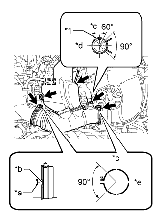
Text in Illustration *1 Paint mark *a Protrusion *b Groove *c Top *d RH *e Front Install the air cleaner hose with the 2 clamps.
- Torque:
- 5.0 N*m { 51 kgf*cm, 44 in.*lbf }
-
Install the bolt.
- Torque:
- 5.0 N*m { 51 kgf*cm, 44 in.*lbf }
-
Connect the vacuum hose and ventilation hose.
Tech Tips
The direction of the hose clamp is indicated in the illustration.
-
Attach the wire harness clamp.
-
-
INSTALL V-BANK COVER
-
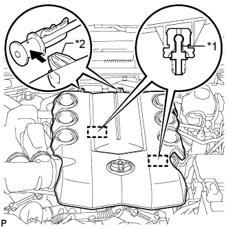
Text in Illustration *1 Pin *2 Hook Attach the 2 V-bank cover hooks to the bracket. Then align the 2 V-bank cover grommets with the 2 pins and press down on the V-bank cover to attach the pins.
-