SFI SYSTEM, Diagnostic DTC:P2431, P2432, P2433, P2436, P2437, P2438

| DTC Code | DTC Name |
|---|---|
| P2431 | Secondary Air Injection System Air Flow / Pressure Sensor Circuit Range / Performance Bank1 |
| P2432 | Secondary Air Injection System Air Flow / Pressure Sensor Circuit Low Bank1 |
| P2433 | Secondary Air Injection System Air Flow / Pressure Sensor Circuit High Bank1 |
| P2436 | Secondary Air Injection System Air Flow / Pressure Sensor Circuit Bank2 |
| P2437 | Open in Secondary Air Injection System Air Flow / Pressure Sensor Circuit Bank2 |
| P2438 | Short in Secondary Air Injection System Air Flow / Pressure Sensor Circuit Bank2 |
DESCRIPTION
Refer to DTC P0412 Click here.
Refer to DTC P0416 Click here.
| DTC No. | DTC Detection Condition | Trouble Area |
|---|---|---|
| P2431 P2436 |
Pressure sensor indicates a value below 45.6 kPa (342 mmHg), or higher than 135 kPa (1013 mmHg) for 5 seconds or more (2 trip detection logic). |
|
| P2432 P2437 |
While the engine is running, voltage output of the pressure sensor is below 0.5 V (1 trip detection logic). |
|
| P2433 P2438 |
While the engine is running, voltage output of the pressure sensor is higher than 4.5 V (1 trip detection logic) |
|
MONITOR DESCRIPTION
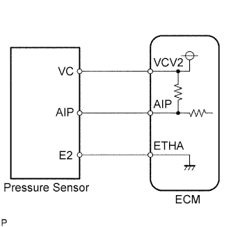
The ECM monitors the pressure inside the air passage of the secondary air injection system using the pressure sensor of the air switching valve assembly. If the ECM detects a malfunction in the sensor or sensor circuit, it stores a DTC.
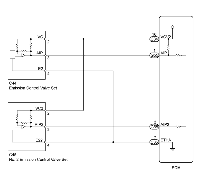
WIRING DIAGRAM
INSPECTION PROCEDURE
Tech Tips
Read freeze frame data using the intelligent tester. Freeze frame data records the engine condition when malfunctions are detected. When troubleshooting, freeze frame data can help determine if the vehicle was moving or stationary, if the engine was warmed up or not, if the air-fuel ratio was lean or rich, and other data from the time the malfunction occurred.
PROCEDURE
-
CHECK HARNESS AND CONNECTOR (PRESSURE SENSOR - ECM)
-
Disconnect the pressure sensor connector.
-
Disconnect the ECM connector.
-
Measure the resistance according to the value(s) in the table below.
Standard Resistance (Check for Open) Tester Connection Condition Specified Condition C44-3 (AIP) - G55-1 (AIP) Always Below 1 Ω C44-2 (VC) - C34-16 (VCV2) Always Below 1 Ω C44-4 (E2) - C35-7 (ETHA) Always Below 1 Ω C45-3 (AIP2) - G55-2 (AIP2) Always Below 1 Ω C45-2 (VC2) - C34-16 (VCV2) Always Below 1 Ω C45-4 (E22) - C35-7 (ETHA) Always Below 1 Ω Standard Resistance (Check for Short) Tester Connection Condition Specified Condition C44-3 (AIP) or G55-1 (AIP) - Body ground Always 10 kΩ or higher C44-2 (VC) or C34-16 (VCV2) - Body ground Always 10 kΩ or higher C45-3 (AIP2) or G55-2 (AIP2) - Body ground Always 10 kΩ or higher C45-2 (VC2) or C34-16 (VCV2) - Body ground Always 10 kΩ or higher -
Reconnect the pressure sensor connector.
-
Reconnect the ECM connector.
NG 
REPAIR OR REPLACE HARNESS OR CONNECTOR
OK 
-
-
INSPECT EMISSION CONTROL VALVE SET (PRESSURE SENSOR)
-
Connect the intelligent tester to the DLC3.
-
Turn the ignition switch to ON and turn the intelligent tester on.
-
Enter the following menus: Powertrain / Engine and ECT / Data List / Air pump pressure (absolute) or Air pump2 pressure (absolute).
-
Check the pressure displayed on the intelligent tester.
Standard pressure 45 to 135 kPa Tech Tips
The intelligent tester displays the air pump pressure as an absolute pressure.
Result Result Proceed to OK A NG (for Bank 1) B NG (for Bank 2) C
B
REPLACE EMISSION CONTROL VALVE SET Click here
C
REPLACE NO. 2 EMISSION CONTROL VALVE SET Click here
A 
REPLACE ECM Click here
-