- Click here
REMOVE COOLER COMPRESSOR ASSEMBLY
- Click here
REMOVE FRONT FENDER SPLASH SHIELD SUB-ASSEMBLY LH
-
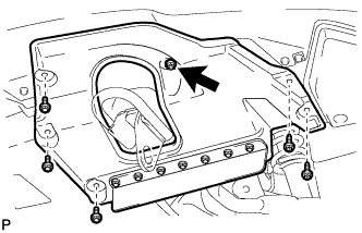
Выверните 3 болта и 2 винта.
-
Поверните фиксатор, указанный стрелкой на рисунке, чтобы снять брызговик левого переднего крыла в сборе.
-
- Click here
REMOVE FRONT FENDER SPLASH SHIELD SUB-ASSEMBLY RH
Tip:Порядок выполнения работ такой же, как для левой стороны.
- Click here
REMOVE NO. 1 ENGINE UNDER COVER SUB-ASSEMBLY
-
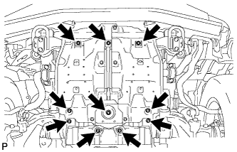
Выверните 10 болтов и снимите нижнюю крышку двигателя № 1 в сборе.
-
- Click here
DRAIN ENGINE COOLANT
CAUTION:Не снимайте пробку радиатора, пока двигатель и радиатор не остынут. Выброс горячей охлаждающей жидкости и пара под давлением может стать причиной серьезных ожогов.
-
Ослабьте пробку сливного крана радиатора.
-
Снимите пробку радиатора и слейте охлаждающую жидкость.
Tip:Слейте охлаждающую жидкость в резервуар и утилизируйте ее в соответствии с местными требованиями.
-
Ослабьте 2 пробки сливных кранов блока цилиндров и слейте охлаждающую жидкость из двигателя.
-
Затяните 2 пробки сливных кранов блока цилиндров.
13 Н*м 130 кгс*см 9 фунт-сила-футов -
Затяните пробку сливного крана радиатора вручную.
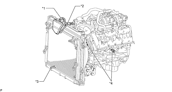
Table 1. Обозначения на рисунке *1 Пробка расширительного бачка *2 Пробка радиатора *3 Пробка сливного крана радиатора *4 Пробка сливного крана блока цилиндров
-
- Click here
REMOVE V-BANK COVER SUB-ASSEMBLY
-
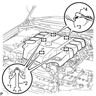
Поднимите переднюю часть декоративной крышки V-образного двигателя, чтобы открепить 3 штифта. Затем снимите 2 крюка декоративной крышки V-образного двигателя с кронштейна, чтобы снять декоративную крышку V-образного двигателя.
Table 2. Обозначения на рисунке *1 Уплотнительная шайба *2 Колпачок *3 Крюк *4 Кронштейн
-
- Click here
REMOVE AIR CLEANER CAP AND HOSE
-
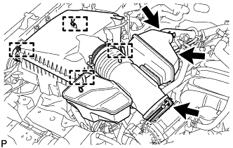
Disconnect the No. 2 PCV hose and No. 1 air hose.
-
Disconnect the mass air flow meter connector and detach the clamp.
-
Detach the 4 clamps.
-
Loosen the hose clamp and remove the air cleaner cap and hose.
-
- Click here
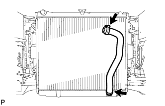
REMOVE NO. 1 RADIATOR HOSE
-
Remove the No. 1 radiator hose.
-
- Click here
REMOVE FAN SHROUD
-
Loosen the 4 nuts holding the fluid coupling fan.
-
Remove the fan and generator V-belt (Click here).
-
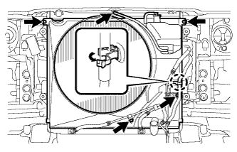
Disconnect the reservoir hose from the upper radiator tank.
-
Detach the claw to open the flexible hose clamp.
-
Remove the 2 bolts and disconnect the oil cooler tube from the fan shroud.
-
Remove the 2 bolts holding the fan shroud.
-
Remove the 4 nuts of the fluid coupling fan, and then remove the shroud together with the fluid coupling fan.
Note:Be careful not to damage the radiator core.
-
Remove the fan pulley from the engine water pump.
-
- Click here
REMOVE NO. 2 RADIATOR HOSE
-
Remove the No. 2 radiator hose.
-
- Click here
REMOVE AIR TUBE SUB-ASSEMBLY
-
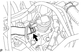
Disconnect the No. 2 air injection system hose from the air switching valve.
-
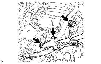
Disconnect the manifold absolute pressure sensor connector and detach the clamp.
-
Remove the 2 bolts and bracket.
-
Remove the bolt and air tube.
-
- Click here
DISCONNECT WATER BY-PASS HOSE
-
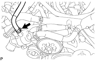
Disconnect the water by-pass hose.
-
- Click here
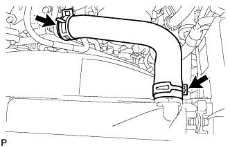
REMOVE NO. 1 WATER BY-PASS HOSE
-
Remove the No. 1 water by-pass hose.
-
- Click here
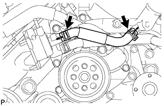
REMOVE NO. 2 WATER BY-PASS PIPE SUB-ASSEMBLY
-
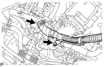
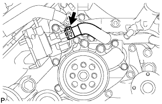
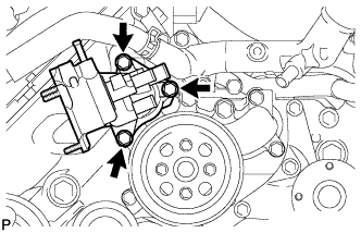
Remove the 2 bolts.
-
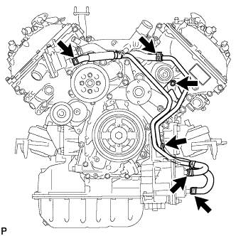
Disconnect the 4 hoses and remove the No. 2 water by-pass pipe.
-
- Click here
DISCONNECT NO. 5 WATER BY-PASS HOSE
-
Disconnect the No. 5 water by-pass hose.
-
- Click here
REMOVE WATER INLET HOUSING
-
Remove the 3 bolts and water inlet housing.
-
Remove the gasket from the engine water pump.
-
- Click here
REMOVE WATER PUMP PULLEY
-
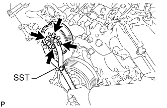
Using SST, hold the water pump pulley.
09960-10010 09962-01000 09963-01000 -
Remove the 4 bolts and water pump pulley.
-
- Click here
REMOVE ENGINE WATER PUMP ASSEMBLY
-
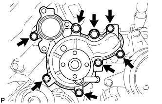
Remove the 8 bolts, engine water pump and gasket.
-