МАСЛЯНЫЙ НАСОС СНЯТИЕ

-
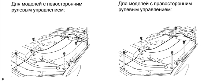
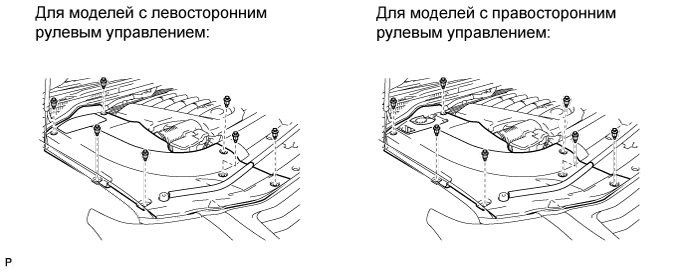
REMOVE ENGINE ROOM SIDE COVER LH
-
Освободите 7 фиксаторов и снимите левую боковую крышку моторного отсека.
-
-
REMOVE ENGINE ROOM SIDE COVER RH
-
Снимите 7 фиксаторов и правую боковую крышку моторного отсека.
-
-
REMOVE UPPER RADIATOR SUPPORT SEAL
-
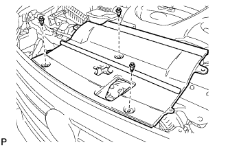
Освободите 3 фиксатора и снимите верхнее уплотнение кронштейна радиатора.
-
-
DISCHARGE FUEL SYSTEM PRESSURE
-
DISCONNECT CABLE FROM NEGATIVE BATTERY TERMINAL
Note
-
w/ Navigation System:
After the engine switch is turned off, the HDD navigation system requires approximately 6 minutes to record various types of memory and settings. As a result, after turning the engine switch off, wait 6 minutes or more before disconnecting the cable from the negative (-) battery terminal.
-
When disconnecting the cable, some systems need to be initialized after the cable is reconnected Click here.
-
-
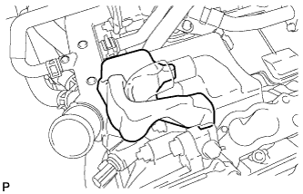
REMOVE V-BANK COVER SUB-ASSEMBLY
-
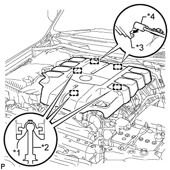
Обозначения на рисунке *1 Уплотнительная шайба *2 Колпачок *3 Крюк *4 Кронштейн Поднимите переднюю часть декоративной крышки V-образного двигателя, чтобы открепить 3 штифта. Затем снимите 2 крюка декоративной крышки V-образного двигателя с кронштейна, чтобы снять декоративную крышку V-образного двигателя.
-
-
REMOVE AIR CLEANER AND HOSE
-
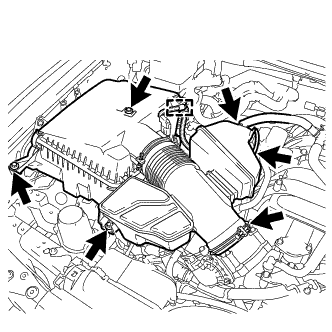
Отсоедините шланг системы принудительной вентиляции картера № 2 и воздушный шланг № 1.
-
Отсоедините разъем датчика массового расхода воздуха и снимите хомут.
-
Выверните 3 болта, ослабьте хомут шланга и снимите воздушный фильтр и шланг.
-
-
REMOVE FRONT FENDER APRON TRIM PACKING A
-
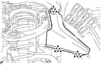
Освободите 3 фиксатора и снимите уплотнение облицовки фартука переднего крыла A.
-
-
DRAIN ENGINE OIL
-
Снимите крышку маслоналивной горловины.
-
Выверните 2 болта и снимите уплотнение защиты картера двигателя № 2.
-
Выверните и снимите пробку сливного отверстия с прокладкой из масляного поддона и слейте масло в емкость.
-
Установите новую прокладку и пробку сливного отверстия масляного поддона.
- Torque:
- 40 Н*м { 408 кгс*см, 30 фунт-сила-футов }
-
Установите уплотнение защиты картера двигателя № 2 и закрепите ее 2 болтами.
- Torque:
- 10 Н*м { 102 кгс*см, 7 фунт-сила-футов }
-
-
REMOVE RADIATOR ASSEMBLY
-
REMOVE INTAKE MANIFOLD
-
DISCONNECT COOLER COMPRESSOR ASSEMBLY
-
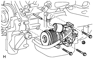
Remove the 3 bolts, nut and stud bolt and disconnect the cooler compressor.
Tech Tips
It is not necessary to completely remove the compressor. With the hoses connected to the compressor, hang the compressor on the vehicle body with a rope.
-
-
REMOVE AIR SWITCHING VALVE ASSEMBLY (for Bank 1)
-
REMOVE AIR SWITCHING VALVE ASSEMBLY (for Bank 2)
-
REMOVE AIR TUBE
-
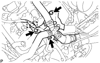
Detach the wire harness clamp.
-
Disconnect the No. 3 air injection system hose.
-
Remove the 2 bolts and air tube.
-
-
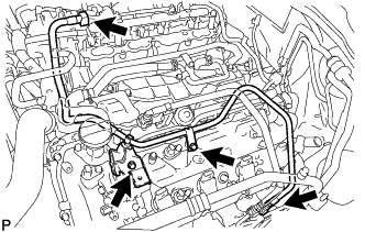
DISCONNECT ENGINE WIRE
-
for Engine Room LH Side:
-
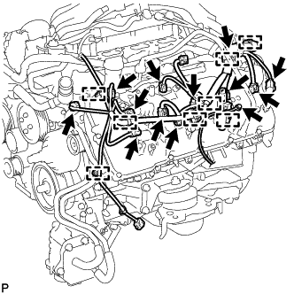
Disconnect the injector connector.
-
Disconnect the 2 camshaft timing oil control valve connectors.
-
Disconnect the 4 ignition coil connectors.
-
Disconnect the 2 VVT sensor connectors.
-
Disconnect the camshaft position sensor connector.
-
Disconnect the engine coolant temperature sensor connector.
-
Disconnect the noise filter connector.
-
Disconnect the 8 clamps.
-
Remove the bolt and ground wire.
-
-
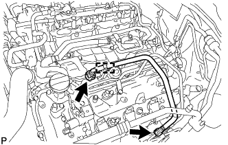
for Engine Room RH Side:
-
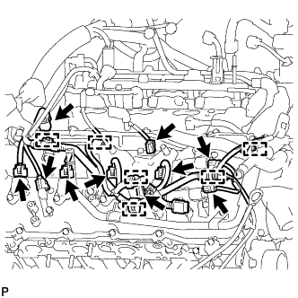
Disconnect the 2 camshaft timing oil control valve connectors.
-
Disconnect the 4 ignition coil connectors.
-
Disconnect the 2 VVT sensor connectors.
-
Disconnect the injector connector.
-
Disconnect the noise filter connector.
-
Disconnect the 6 clamps.
-
-
Remove the bolt and disconnect the clamp and engine wire.
-
-
REMOVE OIL FILTER ELEMENT
-
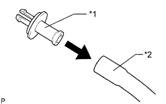
Обозначения на рисунке *1 Патрубок *2 Шланг Подсоедините шланг с внутренним диаметром 15 мм (0,591 дюйма) к трубке.
-
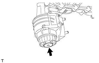
Снимите пробку сливного отверстия масляного фильтра.
-
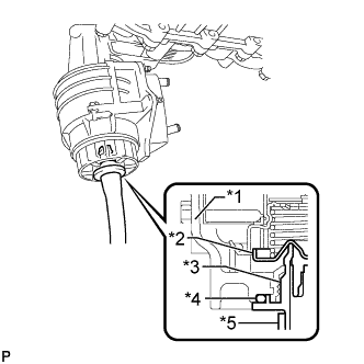
Обозначения на рисунке *1 Пробка *2 Клапан *3 Патрубок *4 Кольцевое уплотнение *5 Шланг Установите трубку на крышку масляного фильтра.
Note
Если вместе с пробкой сливного отверстия снималось кольцевое уплотнение, установите кольцевое уплотнение вместе с трубкой.
Tech Tips
Используйте резервуар для сбора сливаемого масла.
-
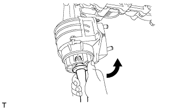
Убедитесь, что масло слито из масляного фильтра. Затем отсоедините трубку и снимите кольцевое уплотнение, как показано на рисунке.
-
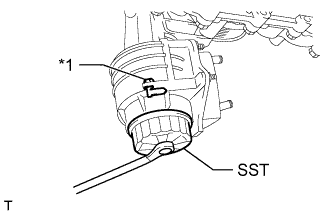
Обозначения на рисунке *1 Фиксатор кронштейна масляного фильтра Снимите крышку масляного фильтра с помощью SST.
- SST
- 09228-06501
Note
Не снимайте фиксатор кронштейна масляного фильтра.
-
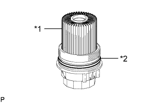
Обозначения на рисунке *1 Фильтрующий элемент масляного фильтра *2 Кольцевое уплотнение Снимите с крышки масляного фильтра фильтрующий элемент масляного фильтра и кольцевое уплотнение.
Note
Чтобы предотвратить повреждение канавки кольцевого уплотнения крышки, снимайте кольцевое уплотнение крышки вручную, не пользуясь какими-либо инструментами.
-
-
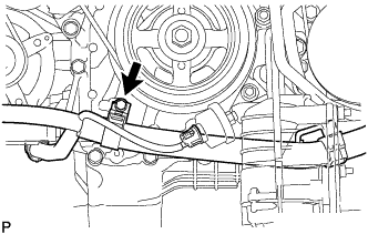
REMOVE OIL PRESSURE SENDER GAUGE ASSEMBLY
-
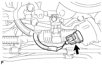
Отсоедините разъем датчика давления масла.
-
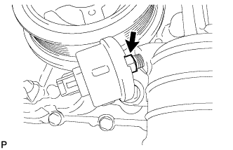
Снимите датчик давления масла.
-
-
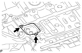
REMOVE NO. 1 OIL COOLER BRACKET
-
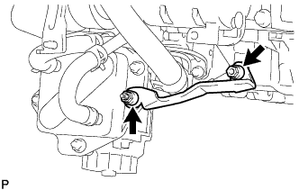
Отверните 2 гайки и снимите кронштейн.
-
Отсоедините провод соединения с массой от блока цилиндров.
-
-
REMOVE OIL FILTER BRACKET
-
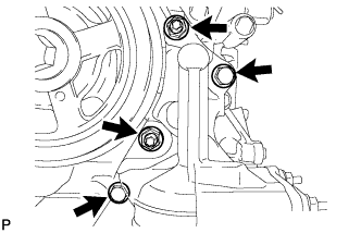
Выверните 2 болта, отверните 2 гайки и снимите кронштейн фильтра.
-
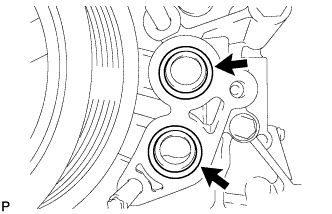
Снимите 2 кольцевых уплотнения.
-
-
REMOVE ENGINE OIL LEVEL DIPSTICK GUIDE
-
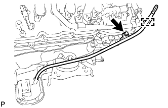
Снимите щуп проверки уровня моторного масла.
-
Освободите зажим жгута электропроводки двигателя.
-
Выверните болт и снимите трубку щупа проверки уровня масла.
-
Снимите с трубки щупа проверки уровня моторного масла кольцевое уплотнение.
-
-
DISCONNECT VANE PUMP ASSEMBLY
-
Disconnect the connector.
-
Remove the 2 bolts and disconnect the vane pump.
-
-
DISCONNECT OIL COOLER TUBE
-
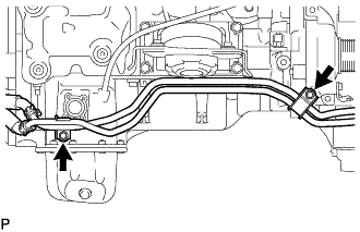
Выверните 2 болта и отсоедините трубку масляного радиатора.
-
-
REMOVE GENERATOR ASSEMBLY
-
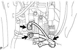
Disconnect the generator connector.
-
Open the terminal cap.
-
Remove the nut and disconnect the generator wire.
-
Remove the bolt and disconnect the wire harness bracket from the generator.
-
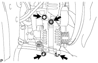
Remove the 3 bolts, nut and generator.
-
Remove the stud bolt.
-
-
REMOVE NO. 4 ENGINE COVER
-
REMOVE NO. 3 ENGINE COVER
-
REMOVE FUEL TUBE SUB-ASSEMBLY
-
Remove the 2 bolts and fuel tube Click here.
-
-
REMOVE FUEL HOSE
-
Remove the fuel pipe clamp.
-
Disconnect the 2 clamps and remove the fuel hose Click here.
-
-
REMOVE NO. 4 AIR TUBE
-
Remove the bolt and bracket.
-
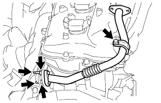
Remove the bolt, 2 nuts, 2 stud bolts, No. 4 air tube and gasket.
-
-
REMOVE NO. 3 AIR TUBE
-
Remove the bolt, 2 nuts, 2 stud bolts, No. 3 air tube and gasket.
-
-
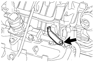
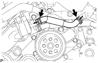
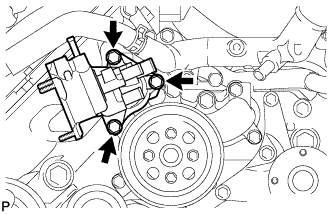
REMOVE NO. 1 WATER BY-PASS PIPE
-
Disconnect the heater water hose.
-
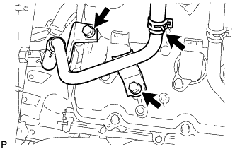
Remove the 2 bolts and disconnect the No. 1 water by-pass pipe.
-
-
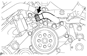
DISCONNECT WATER BY-PASS HOSE
-
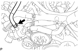
Disconnect the water by-pass hose.
-
-
REMOVE NO. 1 WATER BY-PASS HOSE
-
Remove the No. 1 water by-pass hose.
-
-
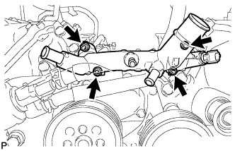
REMOVE NO. 2 WATER BY-PASS PIPE SUB-ASSEMBLY
-
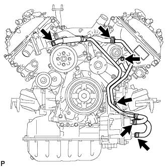
Remove the 2 bolts.
-
Disconnect the 4 hoses and remove the No. 2 water by-pass pipe.
-
-
DISCONNECT NO. 5 WATER BY-PASS HOSE
-
Disconnect the No. 5 water by-pass hose.
-
-
REMOVE WATER BY-PASS PIPE SUB-ASSEMBLY
-
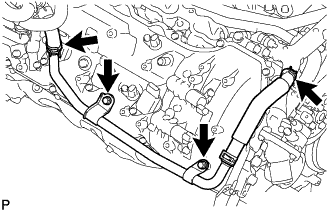
Disconnect the No. 2 water by-pass hose from the front water by-pass joint.
-
Disconnect the heater hose.
-
Remove the 2 bolts and water by-pass pipe sub-assembly.
-
-
REMOVE WATER INLET HOUSING
-
Remove the 3 bolts and water inlet housing.
-
Remove the gasket from the engine water pump.
-
-
REMOVE FRONT WATER BY-PASS JOINT
-
Remove the 4 nuts, water by-pass joint and 2 gaskets.
-
-
REMOVE WATER PUMP PULLEY
-
Temporarily install the water pump pulley with the 4 bolts.
-
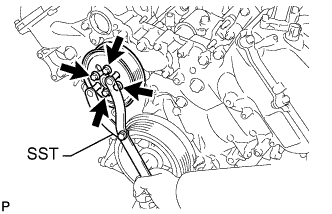
Using SST, hold the water pump pulley and tighten the 4 bolts.
- SST
- 09960-10010 ( 09962-01000, 09963-01000 )
- Torque:
- 21 N*m { 214 kgf*cm, 15 ft.*lbf }
-
-
REMOVE NO. 1 IDLER PULLEY SUB-ASSEMBLY
-
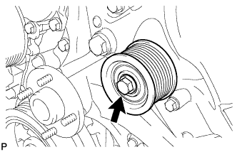
Remove the bolt and No. 1 idler pulley.
-
-
REMOVE FAN BRACKET ASSEMBLY
-
Remove the 5 bolts and fan bracket.
-
-
REMOVE V-RIBBED BELT TENSIONER ASSEMBLY
-
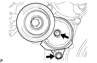
Remove the bolt, 6 mm hexagon bolt and belt tensioner.
-
-
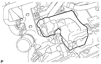
REMOVE IGNITION COIL ASSEMBLY
-
для ряда 1:
-
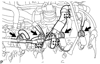
Открепите 4 зажима и отсоедините жгут электропроводки двигателя.
-
Отсоедините разъемы 4 катушек зажигания.
-
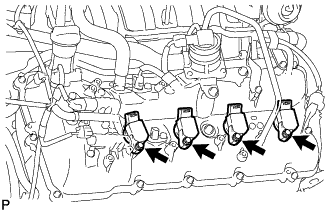
Выверните 4 болта и снимите 4 катушки зажигания.
-
-
для ряда 2:
-
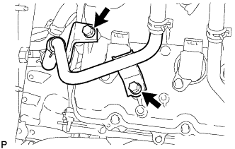
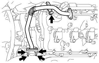
Выверните 2 болта и отсоедините перепускной патрубок охлаждающей жидкости.
-
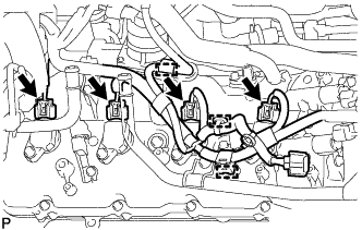
Открепите 3 зажима и отсоедините жгут электропроводки двигателя.
-
Отсоедините разъемы 4 катушек зажигания.
-
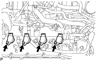
Выверните 4 болта и снимите 4 катушки зажигания.
-
-
-
REMOVE CYLINDER HEAD COVER SUB-ASSEMBLY LH
-
Remove the 14 bolts, seal washer, cylinder head cover sub-assembly LH and cylinder head cover gasket LH.
Tech Tips
Make sure the removed parts are returned to the same places they were removed from.
-
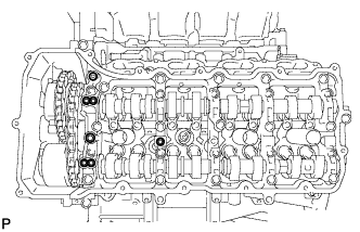
Remove the 5 gaskets from the camshaft bearing caps (No. 2, No. 3).
Text in Illustration 
Gasket
-
-
REMOVE CYLINDER HEAD COVER SUB-ASSEMBLY RH
-
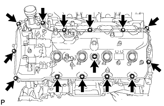
Remove the 14 bolts, seal washer, cylinder head cover sub-assembly RH and cylinder head cover gasket RH.
Tech Tips
Make sure the removed parts are returned to the same places they were removed from.
-
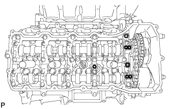
Remove the 5 gaskets from the camshaft bearing caps (No. 1, No. 3).
Text in Illustration Gasket
-
-
REMOVE CRANKSHAFT PULLEY
-
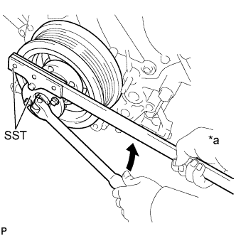
Text in Illustration *a Hold 
Turn Using SST, remove the crankshaft pulley set bolt.
- SST
- 09213-70011
- 09330-00021
-
Temporarily install the pulley set bolt to the crankshaft until 2 or 3 threads are engaged.
-
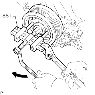
Text in Illustration *a Hold Turn Using the pulley set bolt and SST, remove the crankshaft pulley.
- SST
- 09950-50013 ( 09951-05010, 09952-05010, 09953-05010, 09954-05011 )
-
-
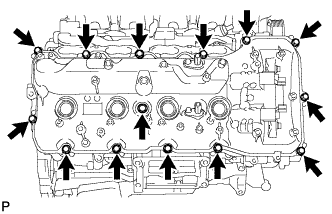
REMOVE TIMING CHAIN COVER SUB-ASSEMBLY
-
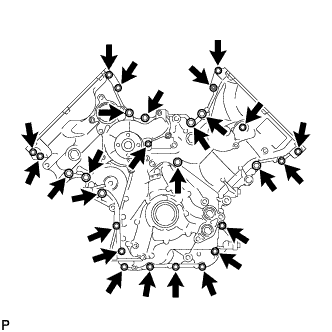
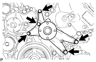
Remove the 26 bolts and nut shown in the illustration.
-
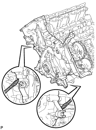
Remove the timing chain cover by prying between it and the cylinder head and cylinder block with a screwdriver as shown in the illustration.
Text in Illustration 
Protective Tape Note
Be careful not to damage the cylinder head, camshaft housing and cylinder block contact surfaces of the chain cover.
Tech Tips
Tape the screwdriver tip before use.
-
Remove the gasket from the cylinder block.
-
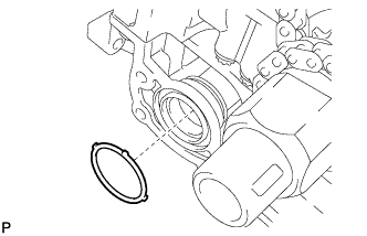
Remove the O-ring from the oil pan.
-
-
REMOVE WATER INLET PIPE
-
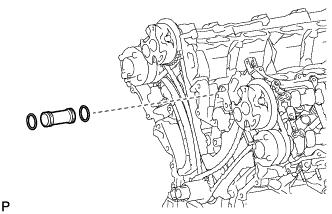
Remove the water inlet pipe.
-
Remove the 2 O-rings from the water inlet pipe.
-
-
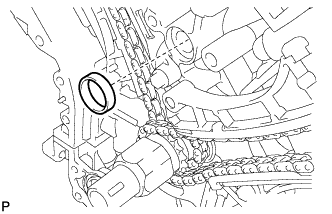
REMOVE FRONT CRANKSHAFT OIL SEAL
-
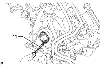
Обозначения на рисунке *1 Защитная клейкая лента С помощью отвертки извлеките передний сальник коленчатого вала.
Note
Будьте осторожны, чтобы не повредить поверхность посадочного углубления переднего сальника коленчатого вала и сам коленчатый вал.
Tech Tips
Конец отвертки перед использованием следует изолировать защитной клейкой лентой.
-