- Click here
REMOVE ENGINE ROOM SIDE COVER LH
-
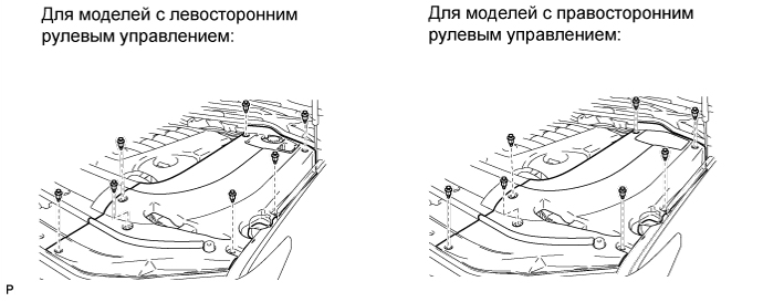
Освободите 7 фиксаторов и снимите левую боковую крышку моторного отсека.
-
- Click here
REMOVE ENGINE ROOM SIDE COVER RH
-
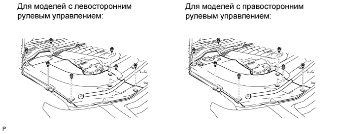
Снимите 7 фиксаторов и правую боковую крышку моторного отсека.
-
- Click here
REMOVE UPPER RADIATOR SUPPORT SEAL
-
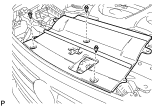
Освободите 3 фиксатора и снимите верхнее уплотнение кронштейна радиатора.
-
- Click here
DISCHARGE FUEL SYSTEM PRESSURE
- Click here
DISCONNECT CABLE FROM NEGATIVE BATTERY TERMINAL
Note:
-
w/ Navigation System:
After the engine switch is turned off, the HDD navigation system requires approximately 6 minutes to record various types of memory and settings. As a result, after turning the engine switch off, wait 6 minutes or more before disconnecting the cable from the negative (-) battery terminal.
-
When disconnecting the cable, some systems need to be initialized after the cable is reconnected (Click here).
-
- Click here
REMOVE V-BANK COVER SUB-ASSEMBLY
-
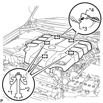
Поднимите переднюю часть декоративной крышки V-образного двигателя, чтобы открепить 3 штифта. Затем снимите 2 крюка декоративной крышки V-образного двигателя с кронштейна, чтобы снять декоративную крышку V-образного двигателя.
Table 1. Обозначения на рисунке *1 Уплотнительная шайба *2 Колпачок *3 Крюк *4 Кронштейн
-
- Click here
REMOVE AIR CLEANER AND HOSE
-
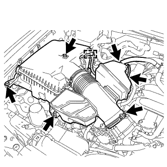
Отсоедините шланг системы принудительной вентиляции картера № 2 и воздушный шланг № 1.
-
Отсоедините разъем датчика массового расхода воздуха и снимите хомут.
-
Выверните 3 болта, ослабьте хомут шланга и снимите воздушный фильтр и шланг.
-
- Click here
REMOVE FRONT FENDER APRON TRIM PACKING A
-
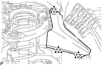
Освободите 3 фиксатора и снимите уплотнение облицовки фартука переднего крыла A.
-
- Click here
DRAIN ENGINE OIL
-
Снимите крышку маслоналивной горловины.
-
Выверните 2 болта и снимите уплотнение защиты картера двигателя № 2.
-
Выверните и снимите пробку сливного отверстия с прокладкой из масляного поддона и слейте масло в емкость.
-
Установите новую прокладку и пробку сливного отверстия масляного поддона.
40 Н*м 408 кгс*см 30 фунт-сила-футов -
Установите уплотнение защиты картера двигателя № 2 и закрепите ее 2 болтами.
10 Н*м 102 кгс*см 7 фунт-сила-футов
-
- Click here
REMOVE RADIATOR ASSEMBLY
- Click here
REMOVE INTAKE MANIFOLD
- Click here
DISCONNECT COOLER COMPRESSOR ASSEMBLY
-
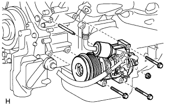
Remove the 3 bolts, nut and stud bolt and disconnect the cooler compressor.
Tip:It is not necessary to completely remove the compressor. With the hoses connected to the compressor, hang the compressor on the vehicle body with a rope.
-
- Click here
REMOVE AIR SWITCHING VALVE ASSEMBLY (for Bank 1)
- Click here
REMOVE AIR SWITCHING VALVE ASSEMBLY (for Bank 2)
- Click here
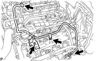
REMOVE AIR TUBE
-
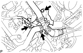
Detach the wire harness clamp.
-
Disconnect the No. 3 air injection system hose.
-
Remove the 2 bolts and air tube.
-
- Click here
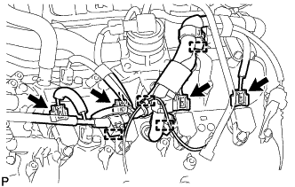
DISCONNECT ENGINE WIRE
-
for Engine Room LH Side:
-
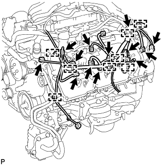
Disconnect the injector connector.
-
Disconnect the 2 camshaft timing oil control valve connectors.
-
Disconnect the 4 ignition coil connectors.
-
Disconnect the 2 VVT sensor connectors.
-
Disconnect the camshaft position sensor connector.
-
Disconnect the engine coolant temperature sensor connector.
-
Disconnect the noise filter connector.
-
Disconnect the 8 clamps.
-
Remove the bolt and ground wire.
-
-
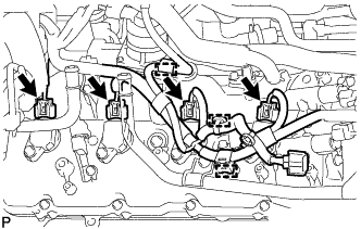
for Engine Room RH Side:
-
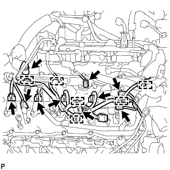
Disconnect the 2 camshaft timing oil control valve connectors.
-
Disconnect the 4 ignition coil connectors.
-
Disconnect the 2 VVT sensor connectors.
-
Disconnect the injector connector.
-
Disconnect the noise filter connector.
-
Disconnect the 6 clamps.
-
-
Remove the bolt and disconnect the clamp and engine wire.
-
- Click here
REMOVE OIL FILTER ELEMENT
-
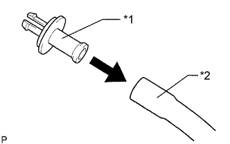
Подсоедините шланг с внутренним диаметром 15 мм (0,591 дюйма) к трубке.
Table 2. Обозначения на рисунке *1 Патрубок *2 Шланг -
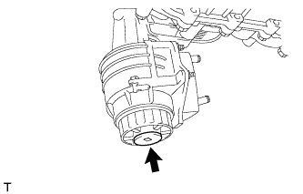
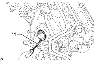
Снимите пробку сливного отверстия масляного фильтра.
-
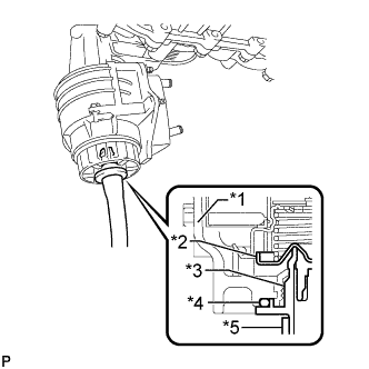
Установите трубку на крышку масляного фильтра.
Table 3. Обозначения на рисунке *1 Пробка *2 Клапан *3 Патрубок *4 Кольцевое уплотнение *5 Шланг Note:Если вместе с пробкой сливного отверстия снималось кольцевое уплотнение, установите кольцевое уплотнение вместе с трубкой.
Tip:Используйте резервуар для сбора сливаемого масла.
-
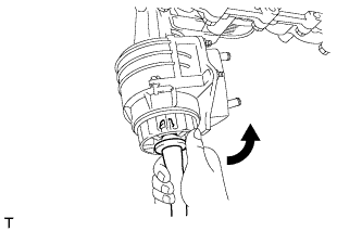
Убедитесь, что масло слито из масляного фильтра. Затем отсоедините трубку и снимите кольцевое уплотнение, как показано на рисунке.
-
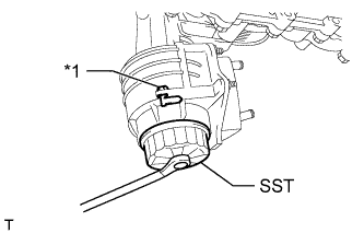
Снимите крышку масляного фильтра с помощью SST.
09228-06501 Table 4. Обозначения на рисунке *1 Фиксатор кронштейна масляного фильтра Note:Не снимайте фиксатор кронштейна масляного фильтра.
-
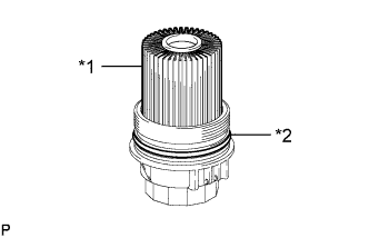
Снимите с крышки масляного фильтра фильтрующий элемент масляного фильтра и кольцевое уплотнение.
Table 5. Обозначения на рисунке *1 Фильтрующий элемент масляного фильтра *2 Кольцевое уплотнение Note:Чтобы предотвратить повреждение канавки кольцевого уплотнения крышки, снимайте кольцевое уплотнение крышки вручную, не пользуясь какими-либо инструментами.
-
- Click here
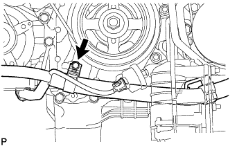
REMOVE OIL PRESSURE SENDER GAUGE ASSEMBLY
-
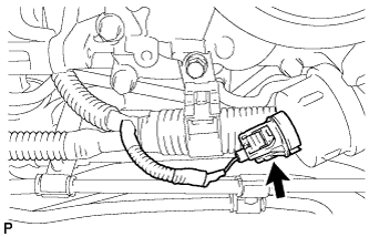
Отсоедините разъем датчика давления масла.
-
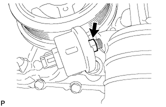
Снимите датчик давления масла.
-
- Click here
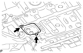
REMOVE NO. 1 OIL COOLER BRACKET
-
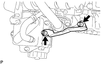
Отверните 2 гайки и снимите кронштейн.
-
Отсоедините провод соединения с массой от блока цилиндров.
-
- Click here
REMOVE OIL FILTER BRACKET
-
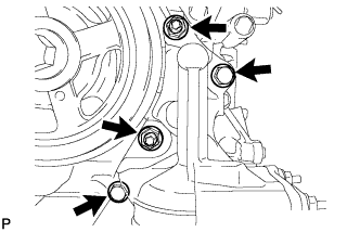
Выверните 2 болта, отверните 2 гайки и снимите кронштейн фильтра.
-
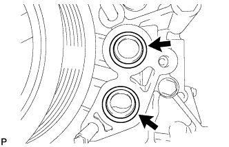
Снимите 2 кольцевых уплотнения.
-
- Click here
REMOVE ENGINE OIL LEVEL DIPSTICK GUIDE
-
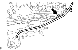
Снимите щуп проверки уровня моторного масла.
-
Освободите зажим жгута электропроводки двигателя.
-
Выверните болт и снимите трубку щупа проверки уровня масла.
-
Снимите с трубки щупа проверки уровня моторного масла кольцевое уплотнение.
-
- Click here
DISCONNECT VANE PUMP ASSEMBLY
-
Disconnect the connector.
-
Remove the 2 bolts and disconnect the vane pump.
-
- Click here
DISCONNECT OIL COOLER TUBE
-
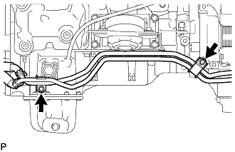
Выверните 2 болта и отсоедините трубку масляного радиатора.
-
- Click here
REMOVE GENERATOR ASSEMBLY
-
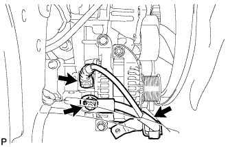
Disconnect the generator connector.
-
Open the terminal cap.
-
Remove the nut and disconnect the generator wire.
-
Remove the bolt and disconnect the wire harness bracket from the generator.
-
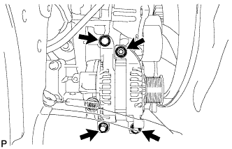
Remove the 3 bolts, nut and generator.
-
Remove the stud bolt.
-
-
Click here
REMOVE NO. 4 ENGINE COVER
-
Click here
REMOVE NO. 3 ENGINE COVER
- Click here
REMOVE FUEL TUBE SUB-ASSEMBLY
-
Remove the 2 bolts and fuel tube (Click here).
-
- Click here
REMOVE FUEL HOSE
-
Remove the fuel pipe clamp.
-
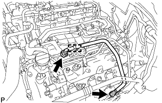
Disconnect the 2 clamps and remove the fuel hose (Click here).
-
- Click here
REMOVE NO. 4 AIR TUBE
-
Remove the bolt and bracket.
-
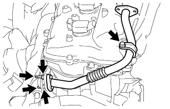
Remove the bolt, 2 nuts, 2 stud bolts, No. 4 air tube and gasket.
-
- Click here
REMOVE NO. 3 AIR TUBE
-
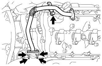
Remove the bolt, 2 nuts, 2 stud bolts, No. 3 air tube and gasket.
-
- Click here
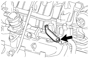
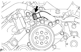
REMOVE NO. 1 WATER BY-PASS PIPE
-
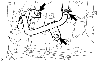
Disconnect the heater water hose.
-
Remove the 2 bolts and disconnect the No. 1 water by-pass pipe.
-
- Click here
DISCONNECT WATER BY-PASS HOSE
-
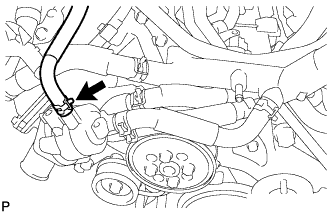
Disconnect the water by-pass hose.
-
- Click here
REMOVE NO. 1 WATER BY-PASS HOSE
-
Remove the No. 1 water by-pass hose.
-
- Click here
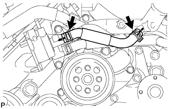
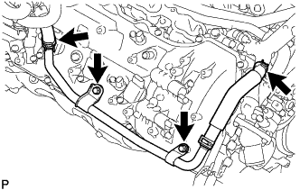
REMOVE NO. 2 WATER BY-PASS PIPE SUB-ASSEMBLY
-
Remove the 2 bolts.
-
Disconnect the 4 hoses and remove the No. 2 water by-pass pipe.
-
- Click here
DISCONNECT NO. 5 WATER BY-PASS HOSE
-
Disconnect the No. 5 water by-pass hose.
-
- Click here
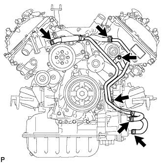
REMOVE WATER BY-PASS PIPE SUB-ASSEMBLY
-
Disconnect the No. 2 water by-pass hose from the front water by-pass joint.
-
Disconnect the heater hose.
-
Remove the 2 bolts and water by-pass pipe sub-assembly.
-
- Click here
REMOVE WATER INLET HOUSING
-
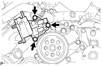
Remove the 3 bolts and water inlet housing.
-
Remove the gasket from the engine water pump.
-
- Click here
REMOVE FRONT WATER BY-PASS JOINT
-
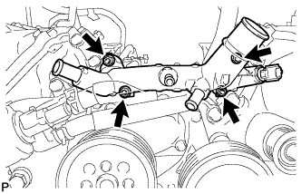
Remove the 4 nuts, water by-pass joint and 2 gaskets.
-
- Click here
REMOVE WATER PUMP PULLEY
-
Temporarily install the water pump pulley with the 4 bolts.
-
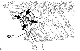
Using SST, hold the water pump pulley and tighten the 4 bolts.
09960-10010 09962-01000 09963-01000 21 N*m 214 kgf*cm 15 ft.*lbf
-
- Click here
REMOVE NO. 1 IDLER PULLEY SUB-ASSEMBLY
-
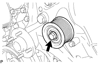
Remove the bolt and No. 1 idler pulley.
-
- Click here
REMOVE FAN BRACKET ASSEMBLY
-
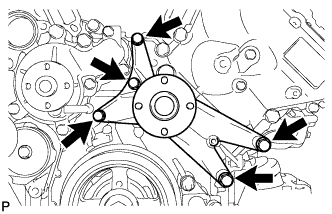
Remove the 5 bolts and fan bracket.
-
- Click here
REMOVE V-RIBBED BELT TENSIONER ASSEMBLY
-
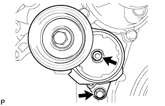
Remove the bolt, 6 mm hexagon bolt and belt tensioner.
-
- Click here
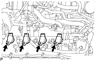
REMOVE IGNITION COIL ASSEMBLY
-
для ряда 1:
-
Открепите 4 зажима и отсоедините жгут электропроводки двигателя.
-
Отсоедините разъемы 4 катушек зажигания.
-
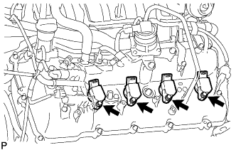
Выверните 4 болта и снимите 4 катушки зажигания.
-
-
для ряда 2:
-
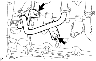
Выверните 2 болта и отсоедините перепускной патрубок охлаждающей жидкости.
-
Открепите 3 зажима и отсоедините жгут электропроводки двигателя.
-
Отсоедините разъемы 4 катушек зажигания.
-
Выверните 4 болта и снимите 4 катушки зажигания.
-
-
- Click here
REMOVE CYLINDER HEAD COVER SUB-ASSEMBLY LH
-
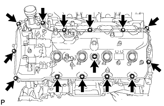
Remove the 14 bolts, seal washer, cylinder head cover sub-assembly LH and cylinder head cover gasket LH.
Tip:Make sure the removed parts are returned to the same places they were removed from.
-
Remove the 5 gaskets from the camshaft bearing caps (No. 2, No. 3).
Table 6. Text in Illustration 
Gasket
-
- Click here
REMOVE CYLINDER HEAD COVER SUB-ASSEMBLY RH
-
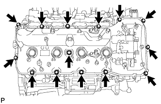
Remove the 14 bolts, seal washer, cylinder head cover sub-assembly RH and cylinder head cover gasket RH.
Tip:Make sure the removed parts are returned to the same places they were removed from.
-
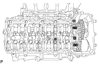
Remove the 5 gaskets from the camshaft bearing caps (No. 1, No. 3).
Table 7. Text in Illustration Gasket
-
- Click here
REMOVE CRANKSHAFT PULLEY
-
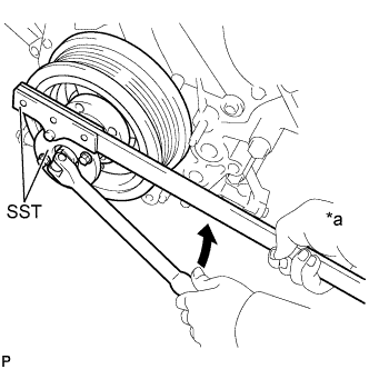
Using SST, remove the crankshaft pulley set bolt.
09213-70011 09330-00021 Table 8. Text in Illustration *a Hold 
Turn -
Temporarily install the pulley set bolt to the crankshaft until 2 or 3 threads are engaged.
-
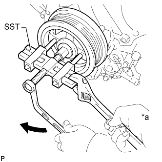
Using the pulley set bolt and SST, remove the crankshaft pulley.
09950-50013 09951-05010 09952-05010 09953-05010 09954-05011 Table 9. Text in Illustration *a Hold Turn
-
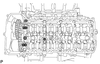
- Click here
REMOVE TIMING CHAIN COVER SUB-ASSEMBLY
-
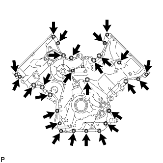
Remove the 26 bolts and nut shown in the illustration.
-
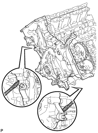
Remove the timing chain cover by prying between it and the cylinder head and cylinder block with a screwdriver as shown in the illustration.
Table 10. Text in Illustration 
Protective Tape Note:Be careful not to damage the cylinder head, camshaft housing and cylinder block contact surfaces of the chain cover.
Tip:Tape the screwdriver tip before use.
-
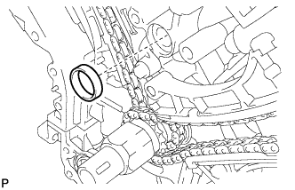
Remove the gasket from the cylinder block.
-
Remove the O-ring from the oil pan.
-
- Click here
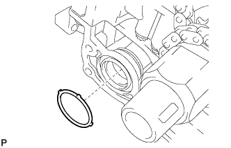
REMOVE WATER INLET PIPE
-
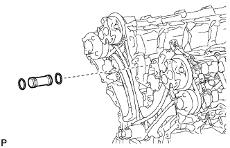
Remove the water inlet pipe.
-
Remove the 2 O-rings from the water inlet pipe.
-
- Click here
REMOVE FRONT CRANKSHAFT OIL SEAL
-
С помощью отвертки извлеките передний сальник коленчатого вала.
Table 11. Обозначения на рисунке *1 Защитная клейкая лента Note:Будьте осторожны, чтобы не повредить поверхность посадочного углубления переднего сальника коленчатого вала и сам коленчатый вал.
Tip:Конец отвертки перед использованием следует изолировать защитной клейкой лентой.
-