- Click here
INSTALL FUEL SUCTION WITH PUMP AND GAUGE TUBE ASSEMBLY
-
Apply a light coat of gasoline or grease to a new gasket, and install it to the fuel tank.
-
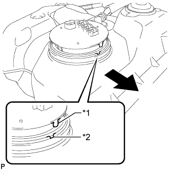
Install the fuel suction with pump and gauge tube into the fuel tank.
Table 1. Text in Illustration *1 Protrusion *2 Groove 
Front Note:Be careful not to bend the arm of the fuel sender gauge.
Tip:Align the protrusion of the fuel suction with pump and gauge tube with the groove of the fuel tank.
-
Put the retainer on the fuel tank. While holding the fuel suction with pump and gauge tube, tighten the retainer 1 complete turn by hand.
-
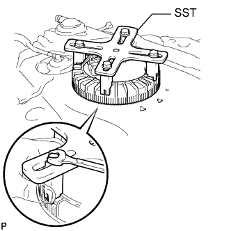
Set SST on the retainer.
09808-14030 Tip:
-
Hold the fuel suction tube assembly upright by hand to make sure that the fuel suction tube gasket is not moved out of position.
-
Engage the claws of SST securely with the fuel pump gauge retainer holes to secure SST.
-
Install SST while pressing the claws of SST against the fuel pump gauge retainer (toward the center of SST).
-
-
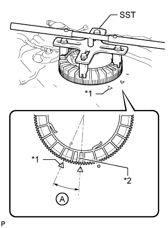
Using SST, tighten the retainer until the mark on the retainer is within range A on the fuel tank as shown in the illustration.
09808-14030 Table 2. Text in Illustration *1 Fuel Tank Side Mark *2 Retainer Side Mark Tip:Fit the tips of SST onto the ribs of the retainer.
-
- Click here
INSTALL FUEL TANK MAIN TUBE, FUEL TANK RETURN TUBE AND NO. 2 FUEL TANK MAIN TUBE SUB-ASSEMBLY
-
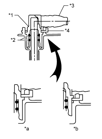
Install the 3 fuel tank tubes with the 3 tube joint clips.
Note:
-
Check that there are no scratches or foreign objects on the connecting parts.
-
Check that the fuel tube joints are inserted securely.
-
Check that the tube joint clips are on the collars of the fuel tube joints.
-
After installing the tube joint clips, check that the fuel tube joints cannot be pulled off.
Table 3. Text in Illustration *1 Fuel Tube Joint *2 O-Ring *3 Fuel Tube *4 Tube Joint Clip *a CORRECT *b INCORRECT -
-
Install the 3 fuel tank tubes to the fuel tank.
-
- Click here
INSTALL FUEL TANK SUB-ASSEMBLY