- Click here
DISCHARGE FUEL SYSTEM PRESSURE
CAUTION:
-
Do not disconnect any part of the fuel system until you have discharged the fuel system pressure.
-
After discharging the fuel pressure, place a cloth or equivalent over fittings as you separate them to reduce the risk of fuel spray on yourself or in the engine compartment.
-
Disconnect the fuel pump ECU connector (Click here).
-
Start the engine. After the engine stops, turn the engine switch off.
Tip:DTC P0171/0174 (system too lean) may be stored.
-
Crank the engine again, and then check that the engine does not start.
-
Loosen the fuel tank cap, and then discharge the pressure in the fuel tank completely.
-
Disconnect the cable from the negative (-) battery terminal.
Note:
-
w/ Navigation System:
After the engine switch is turned off, the HDD navigation system requires approximately 6 minutes to record various types of memory and settings. As a result, after turning the engine switch off, wait 6 minutes or more before disconnecting the cable from the negative (-) battery terminal.
-
When disconnecting the cable, some systems need to be initialized after the cable is reconnected (Click here).
-
-
Connect the fuel pump ECU connector (Click here).
-
- Click here
DISCONNECT CABLE FROM NEGATIVE BATTERY TERMINAL
Note:
-
w/ Navigation System:
After the engine switch is turned off, the HDD navigation system requires approximately 6 minutes to record various types of memory and settings. As a result, after turning the engine switch off, wait 6 minutes or more before disconnecting the cable from the negative (-) battery terminal.
-
When disconnecting the cable, some systems need to be initialized after the cable is reconnected (Click here).
-
- Click here
REMOVE NO. 1 FUEL TUBE PROTECTOR
-
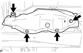
Remove the 4 bolts and No. 1 fuel tube protector.
-
- Click here
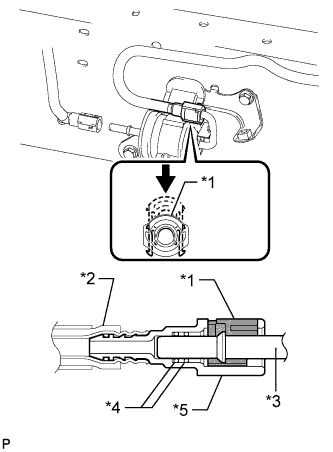
DISCONNECT NO. 2 FUEL MAIN TUBE SUB-ASSEMBLY
-
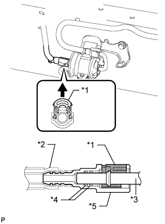
Pull up the retainer and disconnect the No. 2 fuel main tube.
Note:
-
Check for foreign matter in the pipe and around the connector. Clean if necessary. Foreign matter may damage the O-ring or cause leaks in the seal between the pipe and connector.
-
Do not use any tools to separate the pipe and connector.
-
Do not forcefully bend or twist the nylon tube.
-
Check for foreign matter on the pipe seal surface. Clean if necessary.
-
Put the pipe and connector ends in plastic bags to prevent damage and foreign matter contamination.
-
If the pipe and connector are stuck together, pinch the connector between your fingers and turn it carefully to disconnect it.
Table 1. Text in Illustration *1 Retainer *2 Nylon Tube *3 Pipe *4 O-Ring *5 Connector -
-
- Click here
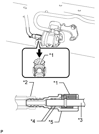
DISCONNECT FUEL MAIN TUBE
-
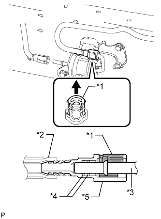
Pull up the retainer and disconnect the fuel main tube.
Note:
-
Check for foreign matter in the pipe and around the connector. Clean if necessary. Foreign matter may damage the O-ring or cause leaks in the seal between the pipe and connector.
-
Do not use any tools to separate the pipe and connector.
-
Do not forcefully bend or twist the nylon tube.
-
Check for foreign matter on the pipe seal surface. Clean if necessary.
-
Put the pipe and connector ends in plastic bags to prevent damage and foreign matter contamination.
-
If the pipe and connector are stuck together, pinch the connector between your fingers and turn it carefully to disconnect it.
Table 2. Text in Illustration *1 Retainer *2 Nylon Tube *3 Pipe *4 O-Ring *5 Connector -
-
- Click here
REMOVE FUEL FILTER ASSEMBLY
-
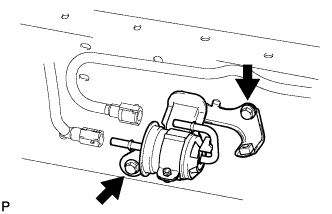
Remove the 2 bolts and fuel filter.
-
- Click here
INSTALL FUEL FILTER ASSEMBLY
-
Install the fuel filter with the 2 bolts.
20 N*m 199 kgf*cm 14 ft.*lbf
-
- Click here
CONNECT FUEL MAIN TUBE
-
Connect the fuel main tube and push the retainer.
Note:
-
Before installing the tube connectors to the pipes, check if there is any damage or foreign matter in the connectors.
-
After the connection, check if the connectors and pipes are securely connected by trying to pull them apart.
Table 3. Text in Illustration *1 Retainer *2 Nylon Tube *3 Pipe *4 O-Ring *5 Connector Tip:Push the parts together firmly until a "click" sound is heard.
-
-
- Click here
CONNECT NO. 2 FUEL MAIN TUBE SUB-ASSEMBLY
-
Connect the No. 2 fuel main tube and push the retainer.
Note:
-
Before installing the tube connectors to the pipes, check if there is any damage or foreign matter in the connectors.
-
After the connection, check if the connectors and pipes are securely connected by trying to pull them apart.
Table 4. Text in Illustration *1 Retainer *2 Nylon Tube *3 Pipe *4 O-Ring *5 Connector Tip:Push the parts together firmly until a "click" sound is heard.
-
-
- Click here
CONNECT CABLE TO NEGATIVE BATTERY TERMINAL
Note:When disconnecting the cable, some systems need to be initialized after the cable is reconnected (Click here).
- Click here
INSPECT FOR FUEL LEAK
-
Make sure that there are no fuel leaks after performing maintenance on the fuel system.
-
Connect the GTS to the DLC3.
-
Turn the engine switch on (IG) and turn the GTS on.
Note:Do not start the engine.
-
Enter the following menus: Powertrain / Engine and ECT / Active Test / Control the Fuel Pump / Speed.
-
Check that there are no leaks from the fuel system.
If there are fuel leaks, repair or replace parts as necessary.
-
Turn the engine switch off.
-
Disconnect the GTS from the DLC3.
-
-
- Click here
INSTALL NO. 1 FUEL TUBE PROTECTOR
-
Install the No. 1 fuel tube protector with the 4 bolts.
29 N*m 296 kgf*cm 21 ft.*lbf
-