- Click here
DISCHARGE FUEL SYSTEM PRESSURE
CAUTION:
-
Do not disconnect any part of the fuel system until you have discharged the fuel system pressure.
-
After discharging the fuel pressure, place a cloth or equivalent over fittings as you separate them to reduce the risk of fuel spray on yourself or in the engine compartment.
-
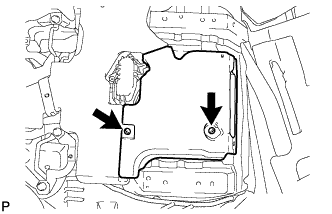
Disconnect the fuel pump ECU connector (Click here).
-
Start the engine. After the engine stops, turn the engine switch off.
Tip:DTC P0171/0174 (system too lean) may be stored.
-
Crank the engine again, and then check that the engine does not start.
-
Loosen the fuel tank cap, and then discharge the pressure in the fuel tank completely.
-
Disconnect the cable from the negative (-) battery terminal.
Note:
-
w/ Navigation System:
After the engine switch is turned off, the HDD navigation system requires approximately 6 minutes to record various types of memory and settings. As a result, after turning the engine switch off, wait 6 minutes or more before disconnecting the cable from the negative (-) battery terminal.
-
When disconnecting the cable, some systems need to be initialized after the cable is reconnected (Click here).
-
-
Connect the fuel pump ECU connector (Click here).
-
- Click here
DISCONNECT CABLE FROM NEGATIVE BATTERY TERMINAL
Note:
-
w/ Navigation System:
After the engine switch is turned off, the HDD navigation system requires approximately 6 minutes to record various types of memory and settings. As a result, after turning the engine switch off, wait 6 minutes or more before disconnecting the cable from the negative (-) battery terminal.
-
When disconnecting the cable, some systems need to be initialized after the cable is reconnected (Click here).
-
- Click here
REMOVE REAR NO. 1 SEAT ASSEMBLY AND REAR NO. 2 SEAT ASSEMBLY
-
Click here
REMOVE FRONT FLOOR CARPET ASSEMBLY
-
Turn over the floor carpet.
Tip:Fold back the floor carpet so that the air duct can be removed.
-
- Click here
REMOVE REAR FLOOR NO. 2 SERVICE HOLE COVER
-
Remove the 2 screws and air duct.
-
Remove the service hole cover.
-
- Click here
REMOVE FUEL TANK CAP ASSEMBLY
- Click here
REMOVE NO. 1 FUEL TANK PROTECTOR SUB-ASSEMBLY
-
Remove the 5 bolts and fuel tank protector.
-
- Click here
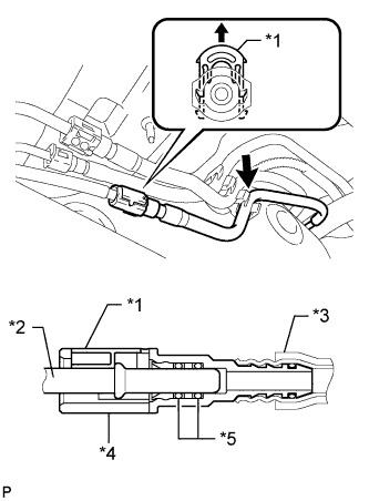
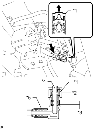
DISCONNECT FUEL TANK MAIN TUBE SUB-ASSEMBLY
-
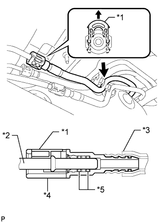
Detach the fuel tube clamp.
-
Pull up the retainer and disconnect the fuel tank main tube.
Note:
-
Check for foreign matter in the pipe and around the connector. Clean if necessary. Foreign matter may damage the O-ring or cause leaks in the seal between the pipe and connector.
-
Do not use any tools to separate the pipe and connector.
-
Do not forcefully bend or twist the nylon tube.
-
Check for foreign matter on the pipe seal surface. Clean if necessary.
-
Put the pipe and connector ends in plastic bags to prevent damage and foreign matter contamination.
-
If the pipe and connector are stuck together, pinch the connector between your fingers and turn it carefully to disconnect it.
Table 1. Text in Illustration *1 Retainer *2 Pipe *3 Nylon Tube *4 Connector *5 O-Ring -
-
- Click here
DRAIN FUEL
-
Connect the cable to the negative (-) battery terminal.
-
Connect the GTS to the DLC3.
-
Turn the engine switch on (IG).
Note:Do not start the engine.
-
Turn the GTS on.
-
Enter the following menus: Powertrain / Engine and ECT / Active Test / Control the Fuel Pump / Speed.
CAUTION:
-
Do not smoke or be near an open flame when working on the fuel system.
-
Secure good ventilation.
-
Keep gasoline away from rubber or leather parts.
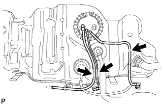
Tip: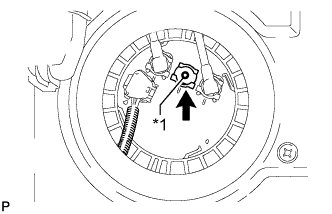
If the fuel pump does not operate, remove the fuel tube joint clip and disconnect the fuel tank return tube, and drain fuel from the port shown in the illustration.
Table 2. Text in Illustration *1 Port -
-
Disconnect the cable from the negative (-) battery terminal.
Note:
-
w/ Navigation System:
After the engine switch is turned off, the HDD navigation system requires approximately 6 minutes to record various types of memory and settings. As a result, after turning the engine switch off, wait 6 minutes or more before disconnecting the cable from the negative (-) battery terminal.
-
When disconnecting the cable, some systems need to be initialized after the cable is reconnected (Click here).
-
-
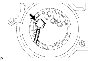
Disconnect the fuel pump and fuel sender gauge connector.
-
- Click here
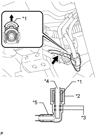
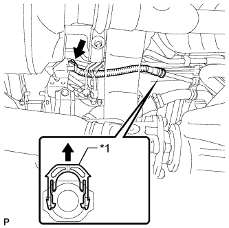
DISCONNECT FUEL TANK RETURN TUBE
-
Detach the fuel tube clamp.
-
Pull up the retainer and disconnect the fuel tank return tube.
Note:
-
Check for foreign matter in the pipe and around the connector. Clean if necessary. Foreign matter may damage the O-ring or cause leaks in the seal between the pipe and connector.
-
Do not use any tools to separate the pipe and connector.
-
Do not forcefully bend or twist the nylon tube.
-
Check for foreign matter on the pipe seal surface. Clean if necessary.
-
Put the pipe and connector ends in plastic bags to prevent damage and foreign matter contamination.
-
If the pipe and connector are stuck together, pinch the connector between your fingers and turn it carefully to disconnect it.
Table 3. Text in Illustration *1 Retainer *2 Pipe *3 Nylon Tube *4 Connector *5 O-Ring -
-
- Click here
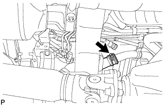
DISCONNECT NO. 2 FUEL MAIN TUBE SUB-ASSEMBLY
-
Detach the fuel tube clamp.
-
Pull up the retainer and disconnect the fuel tank main tube.
Note:
-
Check for foreign matter in the pipe and around the connector. Clean if necessary. Foreign matter may damage the O-ring or cause leaks in the seal between the pipe and connector.
-
Do not use any tools to separate the pipe and connector.
-
Do not forcefully bend or twist the nylon tube.
-
Check for foreign matter on the pipe seal surface. Clean if necessary.
-
Put the pipe and connector ends in plastic bags to prevent damage and foreign matter contamination.
-
If the pipe and connector are stuck together, pinch the connector between your fingers and turn it carefully to disconnect it.
Table 4. Text in Illustration *1 Retainer *2 Connector *3 O-Ring *4 Pipe *5 Nylon Tube -
-
- Click here
DISCONNECT NO. 2 FUEL TANK BREATHER TUBE
-
Detach the fuel tube clamp.
-
Pull up the retainer and disconnect the fuel tank breather tube.
Note:
-
Check for foreign matter in the pipe and around the connector. Clean if necessary. Foreign matter may damage the O-ring or cause leaks in the seal between the pipe and connector.
-
Do not use any tools to separate the pipe and connector.
-
Do not forcefully bend or twist the nylon tube.
-
Check for foreign matter on the pipe seal surface. Clean if necessary.
-
Put the pipe and connector ends in plastic bags to prevent damage and foreign matter contamination.
-
If the pipe and connector are stuck together, pinch the connector between your fingers and turn it carefully to disconnect it.
Table 5. Text in Illustration *1 Retainer *2 Connector *3 O-Ring *4 Pipe *5 Nylon Tube -
-
- Click here
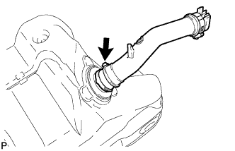
DISCONNECT FUEL TANK BREATHER TUBE
-
Detach the fuel tube clamp.
-
Pull up the retainer and disconnect the fuel tank breather tube from the filler pipe.
Note:
-
Do not use any tools in this procedure.
-
Check for any dirt and foreign matter contamination in the pipe and around the connector. Clean if necessary. Foreign matter may damage the O-ring or cause leaks in the seal between the pipe and connector.
Table 6. Text in Illustration *1 Retainer -
-
- Click here
DISCONNECT FUEL TANK TO FILLER PIPE HOSE
-
Disconnect the hose from the filler pipe.
-
- Click here
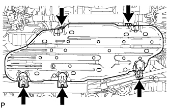
REMOVE FUEL TANK SUB-ASSEMBLY
-
Place an engine lifter under the fuel tank.
-
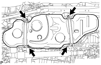
Remove the 2 bolts, 2 clips, 2 pins and 2 fuel tank bands.
-
Slowly lower the engine lifter slightly.
-
- Click here
REMOVE FUEL TANK MAIN TUBE, FUEL TANK RETURN TUBE AND NO. 2 FUEL TANK MAIN TUBE SUB-ASSEMBLY
-
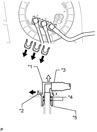
Remove the 3 fuel tube joint clips and pull out the 3 fuel tubes.
Note:
-
Remove any dirt and foreign matter on the fuel tube joint before performing this work.
-
Do not allow any scratches or foreign matter on the parts when disconnecting them, as the fuel tube joint contains the O-rings that seal the plug.
-
Perform this work by hand. Do not use any tools.
-
Do not forcibly bend, twist or turn the nylon tube.
-
Protect the disconnected part by covering it with a plastic bag and tape after disconnecting the fuel tubes.
Table 7. Text in Illustration *1 Tube Joint *2 Tube Joint Clip *3 Fuel Tank Tube *4 O-Ring *5 Fuel Suction Plate -
-
Remove the 3 fuel tubes from the fuel tank.
-
- Click here
REMOVE FUEL SUCTION WITH PUMP AND GAUGE TUBE ASSEMBLY
-
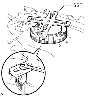
Set SST on the fuel pump gauge retainer.
09808-14030 Tip:
-
Engage the claws of SST securely with the fuel pump gauge retainer holes to secure SST.
-
Install SST while pressing the claws of SST against the fuel pump gauge retainer (towards the center of SST).
-
-
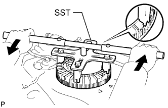
Using SST, loosen the retainer.
09808-14030 Table 8. Text in Illustration 
Turn Note:
-
When the retainer is loosened, be careful as the pump and gauge tube will spring upward from the force of the spring.
-
Remove foreign matter around the fuel suction with pump and gauge before this operation.
Tip:Fit the tips of SST onto the ribs of the retainer.
-
-
Remove the retainer.
-
Remove the fuel suction with pump and gauge tube assembly from the fuel tank.
Note:Be careful not to bend the arm of the fuel sender gauge.
-
Remove the gasket from the fuel tank.
-
- Click here
REMOVE FUEL TANK TO FILLER PIPE HOSE
-
Remove the hose from the fuel tank.
-
- Click here
REMOVE NO. 1 FUEL TANK HEAT INSULATOR
-
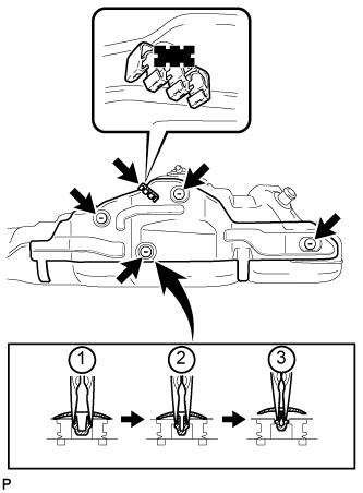
Remove the fuel tube clamp from the heat insulator.
-
Using needle-nose pliers, remove the 4 clips shown in the illustration, and then remove the heat insulator.
-