- Click here
INSTALL CAMSHAFT TIMING OIL CONTROL VALVE ASSEMBLY (for Exhaust Side of Bank 2)
-
Apply a light coat of engine oil to a new O-ring.
-
Install the O-ring to the camshaft timing oil control valve.
-
Install the camshaft timing oil control valve with the bolt.
10 N*m 102 kgf*cm 7 ft.*lbf -
Connect the camshaft timing oil control valve connector.
-
- Click here
INSTALL CAMSHAFT TIMING OIL CONTROL VALVE ASSEMBLY (for Intake Side of Bank 2)
-
Apply a light coat of engine oil to a new O-ring.
-
Install the O-ring to the camshaft timing oil control valve.
-
Install the camshaft timing oil control valve with the bolt.
10 N*m 102 kgf*cm 7 ft.*lbf -
Connect the camshaft timing oil control valve connector.
-
Connect the air pipe with the bolt.
10 N*m 102 kgf*cm 7 ft.*lbf -
Attach the clamp and connect the throttle body connector.
-
- Click here
INSTALL CAMSHAFT TIMING OIL CONTROL VALVE ASSEMBLY (for Intake Side of Bank 1)
-
Apply a light coat of engine oil to a new O-ring.
-
Install the O-ring to the camshaft timing oil control valve.
-
Install the camshaft timing oil control valve with the bolt.
10 N*m 102 kgf*cm 7 ft.*lbf -
Connect the camshaft timing oil control valve connector.
-
- Click here
INSTALL CAMSHAFT TIMING OIL CONTROL VALVE ASSEMBLY (for Exhaust Side of Bank 1)
-
Apply a light coat of engine oil to a new O-ring.
-
Install the O-ring to the camshaft timing oil control valve.
-
Install the camshaft timing oil control valve with the bolt.
10 N*m 102 kgf*cm 7 ft.*lbf -
Connect the camshaft timing oil control valve connector.
-
- Click here
INSTALL AIR CLEANER CAP AND HOSE
-
Install the air cleaner cap and hose, and then tighten the hose clamp.
2.5 N*m 25 kgf*cm 22 in.*lbf -
Attach the 4 clamps.
-
Connect the mass air flow meter connector and attach the clamp.
-
Connect the No. 2 PCV hose and No. 1 air hose.
-
- Click here
INSTALL V-BANK COVER SUB-ASSEMBLY
-
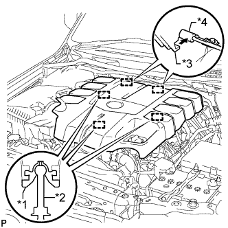
Совместите 2 крюка крышки V-образного двигателя с кронштейном. Затем совместите 3 уплотнительных шайбы декоративной крышки V-образного двигателя с 3 штифтами и нажмите на декоративную крышку V-образного двигателя, чтобы закрепить штифты.
Table 1. Обозначения на рисунке *1 Уплотнительная шайба *2 Штифт *3 Крюк *4 Кронштейн
-
- Click here
INSTALL UPPER RADIATOR SUPPORT SEAL
-
Установите верхнее уплотнение кронштейна радиатора и закрепите его 3 фиксаторами.
-
- Click here
INSTALL ENGINE ROOM SIDE COVER RH
-
Установите правую боковую крышку моторного отсека и закрепите ее 7 фиксаторами.
-
- Click here
INSTALL ENGINE ROOM SIDE COVER LH
-
Установите левую боковую крышку моторного отсека и закрепите ее 7 фиксаторами.
-