TURN SIGNAL FLASHER ASSEMBLY (for RHD) INSTALLATION

-
INSTALL TURN SIGNAL FLASHER ASSEMBLY
-
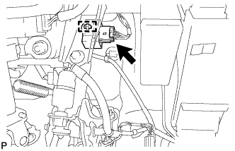
Engage the clamp and install the turn signal flasher assembly.
-
Connect the connector.
-
-
INSTALL DRIVER SIDE KNEE AIRBAG ASSEMBLY
-
Check that the engine switch is off.
-
Check that the battery negative (-) cable is disconnected.
CAUTION:
Wait at least 90 seconds after disconnecting the cable from the negative (-) battery terminal to disable the SRS system.
-
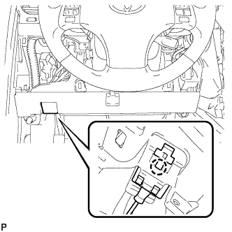
Connect the driver side knee airbag connector to the driver side knee airbag assembly.
Note
When connecting the airbag connector, take care not to damage the airbag wire harness.
-
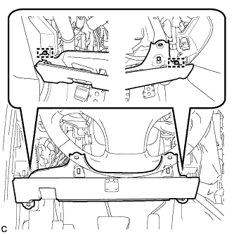
Temporarily install the driver side knee airbag assembly with the 2 pins.
-
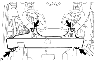
Install the driver side knee airbag assembly with the 4 bolts.
- Torque:
- 10 N*m { 102 kgf*cm, 7 ft.*lbf }
-
Install the hood lock control cable with the claw.
-
-
INSTALL LOWER INSTRUMENT PANEL FINISH PANEL SUB-ASSEMBLY
-
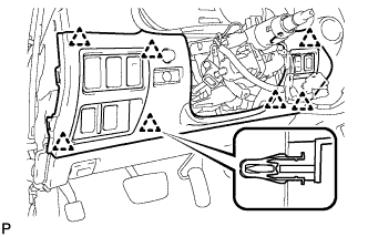
Connect the connectors.
-
Engage the 7 clips to install the lower instrument panel finish panel sub-assembly.
-
-
INSTALL NO. 1 INSTRUMENT PANEL UNDER COVER SUB-ASSEMBLY
-
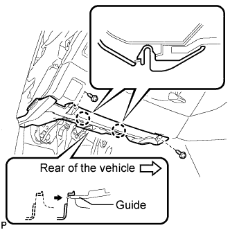
Connect the connectors.
-
Insert the No. 1 instrument panel under cover sub-assembly into the guide as shown in the illustration.
-
Engage the 2 claws.
-
Install the No. 1 instrument panel under cover sub-assembly with the 2 screws <D>.
-
-
INSTALL SIDE INSTRUMENT PANEL RH
-
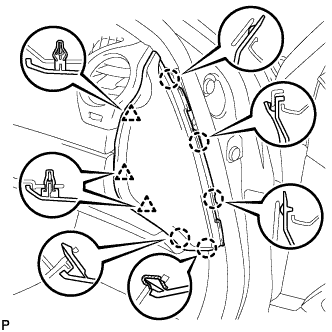
Engage the 5 claws and 3 clips to install the side instrument panel RH.
-
-
INSTALL FRONT DOOR OPENING TRIM COVER RH
Tech Tips
Use the same procedure for the RH side and LH side Click here.
-
INSTALL FRONT DOOR SCUFF PLATE RH
Tech Tips
Use the same procedure for the RH side and LH side Click here.
-
CONNECT CABLE TO NEGATIVE BATTERY TERMINAL
Note
Some systems need to be initialized after the cable is reconnected Click here.
-
INSPECT SRS WARNING LIGHT
-
Inspect the SRS warning light Click here.
-