LIGHTING SYSTEM Speed Signal Circuit
DESCRIPTION
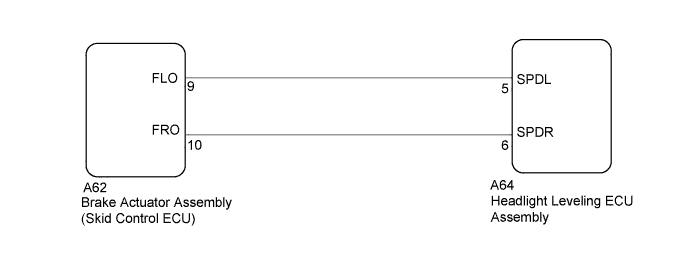
The headlight leveling ECU assembly receives front wheel speed sensor signals from the skid control ECU.
WIRING DIAGRAM
INSPECTION PROCEDURE
PROCEDURE
-
CHECK DTC (VEHICLE STABILITY CONTROL SYSTEM)
-
Check that vehicle stability control system DTCs are not output.
OK VSC system DTC is not output.
NG 
GO TO VEHICLE STABILITY CONTROL SYSTEM Click here
OK 
-
-
CHECK SPEED SENSOR SIGNAL WAVEFORM
-
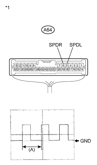
Text in Illustration *1 Component with harness connected
(Headlight Leveling ECU Assembly)
Check the speed signal waveform.
-
Connect an oscilloscope to terminals A64-5 (SPDL) and body ground or terminals A64-6 (SPDR) and body ground.
-
Turn the engine switch on (IG).
-
Turn the front wheels slowly.
-
-
Check the signal waveform according to the condition(s) in the table below.
Item Condition Tool setting 5 V / DIV., 20 ms / DIV. Vehicle condition Wheels being rotated OK The waveform is similar to that shown in the illumination. Tech Tips
When the system is functioning normally, one wheel revolution generates 4 pulses. As the vehicle speed increases, the width indicated by (A) in the illustration narrows.
NG 
CHECK HARNESS AND CONNECTOR (HEADLIGHT LEVELING ECU ASSEMBLY - SKID CONTROL ECU) Click here
OK 
PROCEED TO NEXT SUSPECTED AREA SHOWN IN PROBLEM SYMPTOMS TABLE Click here
-
-
CHECK HARNESS AND CONNECTOR (HEADLIGHT LEVELING ECU ASSEMBLY - SKID CONTROL ECU)
-
Disconnect the A64 headlight leveling ECU assembly connector.
-
Disconnect the A62 brake actuator assembly (skid control ECU) connector.
-
Measure the resistance according to the value(s) in the table below.
Standard Resistance Tester Connection Condition Specified Condition A62-10 (FRO) - A64-6 (SPDR) Always Below 1 Ω A62-9 (FLO) - A64-5 (SPDL) Always Below 1 Ω A64-6 (SPDR) - Body ground Always 10 kΩ or higher A64-5 (SPDL) - Body ground Always 10 kΩ or higher
NG
REPAIR OR REPLACE HARNESS OR CONNECTOR
OK
-
-
INSPECT HEADLIGHT LEVELING ECU ASSEMBLY (OUTPUT VOLTAGE)
-
Disconnect the A62 skid control ECU connector.
-
Measure the voltage according to the value(s) in the table below.
Standard Voltage Tester Connection Condition Specified Condition A62-9 (FLO) - Body ground Engine switch on (IG) 10 to 14 V A62-10 (FRO) - Body ground Engine switch on (IG) 10 to 14 V
NG
REPLACE HEADLIGHT LEVELING ECU ASSEMBLY Click here
OK
REPLACE BRAKE ACTUATOR ASSEMBLY (SKID CONTROL ECU) Click here
-