LIGHTING SYSTEM AFS OFF Switch Circuit
DESCRIPTION
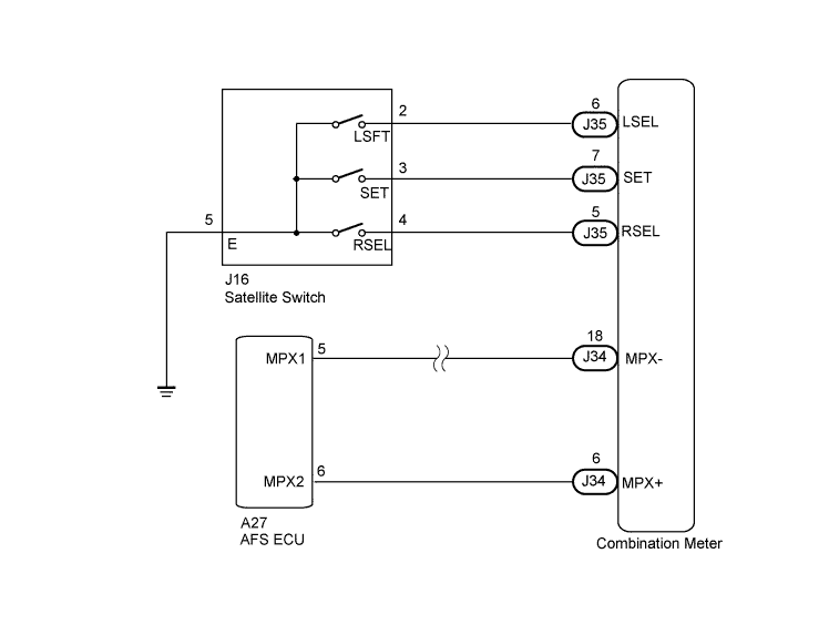
The AFS OFF switch uses the multiplex communication system. First make sure that the multiplex communication system is functioning normally before troubleshooting the AFS OFF switch.
WIRING DIAGRAM
INSPECTION PROCEDURE
PROCEDURE
-
CHECK MULTIPLEX COMMUNICATION SYSTEM
Refer to How to Proceed with Troubleshooting Click here.
If the multiplex communication system is operating normally, proceed to the next step.
NEXT 
-
PERFORM ACTIVE TEST USING INTELLIGENT TESTER
-
Connect the intelligent tester to the DLC3.
-
Turn the engine switch on (IG).
-
Turn the intelligent tester on.
-
Enter the following menus: Body / Combination Meter / Active Test.
-
Check the operation.
Combination Meter Tester Display Test Part Control Range Diagnostic Note Indicat. AFS AFS ON/OFF indicator light ON/OFF - OK AFS ON/OFF indicator comes on.
NG 
GO TO COMBINATION METER SYSTEM Click here
OK
-
-
READ VALUE USING INTELLIGENT TESTER
-
Connect the intelligent tester to the DLC3.
-
Turn the engine switch on (IG).
-
Turn the intelligent tester on.
-
Turn the clearance sonar main switch on.
-
Enter the following menus: Body / AFS / Data List.
-
Read the display on the intelligent tester.
AFS (AFS ECU) Tester Display Measurement Item/Range Normal Condition Diagnostic Note AFS OFF Switch AFS setting / ON or OFF ON: AFS ON
OFF: AFS OFF
- OK Normal conditions listed above are displayed.
NG 
CHECK SATELLITE SWITCH Click here
OK 
REPLACE AFS ECU Click here
-
-
CHECK SATELLITE SWITCH
-
By using the satellite switch (RH switch, ON/OFF switch, LH switch), check the AFS ON/OFF indicator comes on Click here.
OK AFS ON/OFF indicator comes on.
NG
GO TO COMBINATION METER SYSTEM Click here
OK
PROCEED TO NEXT CIRCUIT INSPECTION SHOWN IN PROBLEM SYMPTOMS TABLE Click here
-