LIGHTING SYSTEM AFS ECU Power Source Circuit
DESCRIPTION
This circuit detects the state of the engine switch. The AFS ECU receives it from the engine switch.
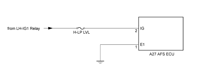
WIRING DIAGRAM
INSPECTION PROCEDURE
PROCEDURE
-
READ VALUE USING INTELLIGENT TESTER
-
Connect the intelligent tester to the DLC3.
-
Turn the engine switch on (IG).
-
Turn the intelligent tester on.
-
Enter the following menus: Body / AFS / Data List.
-
Read the display on the intelligent tester.
AFS (AFS ECU) Tester Display Measurement Item/Range Normal Condition Diagnostic Note +B Battery voltage value / 0 to 20 Engine switch off: Below 1 V
Engine switch on (IG): 11 to 14 V
- OK Condition sign can be displayed.
NG 
CHECK HARNESS AND CONNECTOR (AFS ECU - BODY GROUND) Click here
OK 
PROCEED TO NEXT CIRCUIT INSPECTION SHOWN IN PROBLEM SYMPTOMS TABLE Click here
-
-
CHECK HARNESS AND CONNECTOR (AFS ECU - BODY GROUND)
-
Disconnect the A27 AFS ECU connector.
-
Measure the resistance according to the value(s) in the table below.
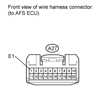
Standard Resistance Tester Connection Condition Specified Condition A27-1 (E1) - Body ground Always Below 1 Ω
NG 
REPAIR OR REPLACE HARNESS OR CONNECTOR (AFS ECU - BODY GROUND)
OK 
-
-
CHECK HARNESS AND CONNECTOR (AFS ECU - BATTERY)
-
Disconnect the A27 AFS ECU connector.
-
Measure the voltage according to the value(s) in the table below.
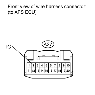
Standard Voltage Tester Connection Switch Condition Specified Condition A27-2 (IG) - Body ground Engine switch on (IG) 11 to 14 V
NG
REPAIR OR REPLACE HARNESS OR CONNECTOR (AFS ECU - BATTERY)
OK
REPLACE AFS ECU Click here
-