LIGHTING SYSTEM Height Control Sensor Circuit
DESCRIPTION
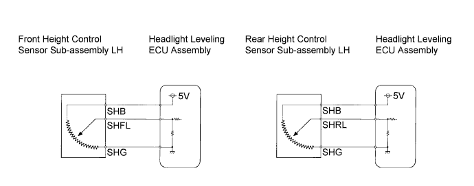
This circuit provides power to operate the height control sensor. The headlight leveling ECU assembly calculates a height value from the height control sensor signal and the voltage at the power source of the height control sensor. The voltage at the power source of the height control sensor is corrected when SHFL or SHRL is detected.
WIRING DIAGRAM
INSPECTION PROCEDURE
PROCEDURE
-
INSPECT FRONT HEIGHT CONTROL SENSOR SUB-ASSEMBLY LH
-
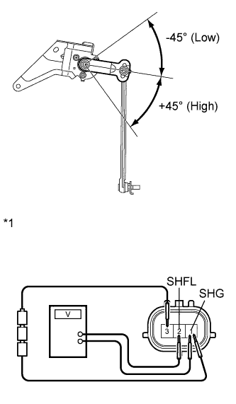
Text in Illustration *1 Component without harness connected
(Front Height Control Sensor Sub-Assembly LH)
Connect 3 dry cell batteries (1.5 V) in series.
-
Remove the front height control sensor sub-assembly LH.
-
Connect a positive (+) lead from the batteries to terminal 3 and a negative (-) lead from the batteries to terminal 1.
-
Measure the voltage between terminals 2 and 1 while slowly moving the link up and down.
Standard Voltage Tester Connection Condition Specified Condition 2 (SHFL) - 1 (SHG) +45° Approx. 4.05 V 2 (SHFL) - 1 (SHG) 0° (Normal) Approx. 2.25 V 2 (SHFL) - 1 (SHG) -45° (Low) Approx. 0.45 V
NG 
REPLACE FRONT HEIGHT CONTROL SENSOR SUB-ASSEMBLY LH Click here
OK 
-
-
INSPECT REAR HEIGHT CONTROL SENSOR SUB-ASSEMBLY LH
-
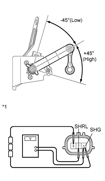
Text in Illustration *1 Component without harness connected
(Rear Height Control Sensor Sub-Assembly LH)
Connect 3 dry cell batteries (1.5 V) in series.
-
Remove the rear height control sensor sub-assembly LH.
-
Connect a positive (+) lead from the batteries to terminal 3 and a negative (-) lead from the batteries to terminal 1.
-
Measure the voltage between terminals 2 and 1 while slowly moving the link up and down.
Standard Voltage Tester Connection Condition Specified Condition 2 (SHRL) - 1 (SHG) +45° Approx. 4.05 V 2 (SHRL) - 1 (SHG) 0° (Normal) Approx. 2.25 V 2 (SHRL) - 1 (SHG) -45° (Low) Approx. 0.45 V
NG
REPLACE REAR HEIGHT CONTROL SENSOR SUB-ASSEMBLY LH Click here
OK
-
-
CHECK HARNESS AND CONNECTOR (HEADLIGHT LEVELING ECU - HEIGHT CONTROL SENSOR (FR OR RR))
-
Check the wire harness between the headlight leveling ECU assembly and front height control sensor sub-assembly LH.
-
Disconnect the W2 front height control sensor sub-assembly connector.
-
Disconnect the A64 headlight leveling ECU assembly connector.
-
Measure the resistance according to the value(s) in the table below.
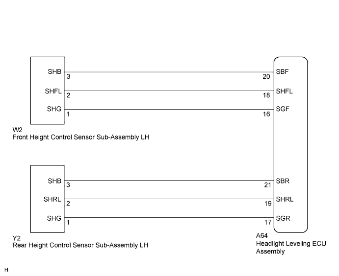
Standard Resistance Tester Connection Condition Specified Condition A64-20 (SBF) - W2-3 (SHB) Always Below 1 Ω A64-18 (SHFL) - W2-2 (SHFL) Always Below 1 Ω A64-16 (SGF) - W2-1 (SHG) Always Below 1 Ω A64-20 (SBF) - Body ground Always 10 kΩ or higher A64-18 (SHFL) - Body ground Always 10 kΩ or higher A64-16 (SGF) - Body ground Always 10 kΩ or higher
-
-
Check the wire harness between the headlight leveling ECU assembly and rear height control sensor sub-assembly LH.
-
Disconnect the Y2 rear height control sensor sub-assembly LH connector.
-
Disconnect the A64 headlight leveling ECU assembly connector.
-
Measure the resistance according to the value(s) in the table below.
Standard Resistance Tester Connection Condition Specified Condition A64-21 (SBR) - Y2-3 (SHB) Always Below 1 Ω A64-19 (SHRL) - Y2-2 (SHRL) Always Below 1 Ω A64-17 (SGR) - Y2-1 (SHG) Always Below 1 Ω A64-21 (SBR) - Body ground Always 10 kΩ or higher A64-19 (SHRL) - Body ground Always 10 kΩ or higher A64-17 (SGR) - Body ground Always 10 kΩ or higher
-
NG
REPAIR OR REPLACE HARNESS OR CONNECTOR
OK 
PROCEED TO NEXT SUSPECTED AREA SHOWN IN PROBLEM SYMPTOMS TABLE Click here
-