LIGHTING SYSTEM Headlight Leveling ECU Power Source Circuit
DESCRIPTION
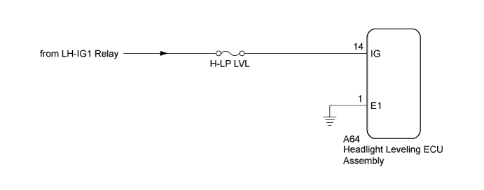
This circuit is uses to detect the on (IG) state of the power source circuit. The headlight leveling ECU assembly receives a signal from the LH-IG1 relay.
WIRING DIAGRAM
INSPECTION PROCEDURE
PROCEDURE
-
INSPECT FUSE (H-LP LVL)
-
Remove the H-LP LVL fuse from the cowl side junction block LH.
-
Measure the resistance of the fuse.
Standard resistance Below 1 Ω
NG 
REPLACE FUSE
OK 
-
-
CHECK HARNESS AND CONNECTOR (HEADLIGHT LEVELING ECU ASSEMBLY - BATTERY AND BODY GROUND)
-
Disconnect the A64 headlight leveling ECU assembly connector.
-
Measure the voltage and resistance of the wire harness side connector.
Standard voltage Tester Connection Condition Specified Condition A64-14 (IG) - A64-1 (E1) Engine switch on (IG) 11 to 14 V Standard resistance Tester Connection Condition Specified Condition A64-1 (E1) - Body ground Always Below 1 Ω
NG
REPAIR OR REPLACE HARNESS OR CONNECTOR
OK 
PROCEED TO NEXT SUSPECTED AREA SHOWN IN PROBLEM SYMPTOMS TABLE Click here
-