LIGHTING SYSTEM Generator Signal Circuit
DESCRIPTION
The headlight leveling ECU assembly uses the ALTL signal as the engine running signal to judge whether to operate the automatic headlight beam level control system.
WIRING DIAGRAM
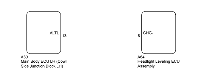
INSPECTION PROCEDURE
PROCEDURE
-
INSPECT MAIN BODY ECU LH (COWL SIDE JUNCTION BLOCK LH) (INPUT VOLTAGE)
-
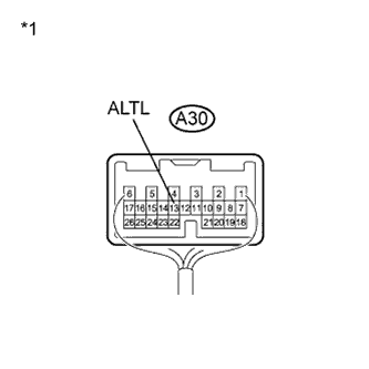
Text in Illustration *1 Component with harness connected
(Main Body ECU LH (Cowl Side Junction Block LH))
Measure the voltage according to the value(s) in the table below.
Standard Voltage Tester Connection Condition Specified Condition A30-13 (ALTL) - Body ground Engine running 11 to 14 V
NG 
CHECK HARNESS AND CONNECTOR (HEADLIGHT LEVELING ECU ASSEMBLY - MAIN BODY ECU LH) Click here
OK 
PROCEED TO NEXT SUSPECTED AREA SHOWN IN PROBLEM SYMPTOMS TABLE Click here
-
-
CHECK HARNESS AND CONNECTOR (HEADLIGHT LEVELING ECU ASSEMBLY - MAIN BODY ECU LH)
-
Disconnect the A64 headlight leveling ECU assembly connector.
-
Disconnect the A30 main body ECU LH connector.
-
Measure the resistance according to the value(s) in the table below.
Standard Resistance Tester Connection Condition Specified Condition A64-8 (CHG-) - A30-13 (ALTL) Always Below 1 Ω A64-8 (CHG-) - Body ground Always 10 kΩ or higher
NG 
REPAIR OR REPLACE HARNESS OR CONNECTOR
OK
PROCEED TO NEXT SUSPECTED AREA SHOWN IN PROBLEM SYMPTOMS TABLE Click here
-