LIGHTING SYSTEM Light Control Switch Circuit
DESCRIPTION
The combination switch ECU (windshield wiper switch assembly) receives the following switch information:
-
Light control switch position is Off, Tail, Head, or Auto
-
Headlight dimmer switch position is High, Low, or Flash (Pass)
-
Turn signal switch position is LH, RH, or Off
-
Front fog light switch position is On or Off
-
Rear fog light switch position is On or Off
The combination switch ECU then converts these signals to BEAN signals and sends them to each ECU via the multiplex communication system.
The headlight dimmer switch assembly includes the light control, headlight dimmer, turn signal, and fog light switches.
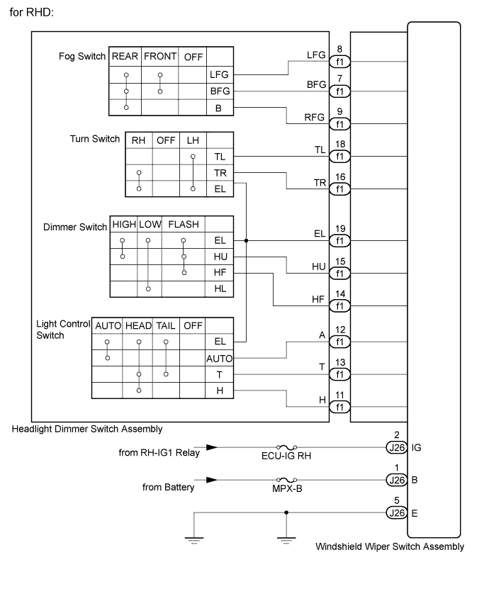
WIRING DIAGRAM

INSPECTION PROCEDURE
PROCEDURE
-
READ VALUE USING INTELLIGENT TESTER
-
Connect the intelligent tester to the DLC3.
-
Turn the engine switch on (IG).
-
Turn the intelligent tester on.
-
Enter the following menus: Body / Combination Switch / Data List.
-
Read the display on the intelligent tester.
Combination Switch (Windshield Wiper Switch Assembly) Tester Display Measurement Item/Range Normal Condition Diagnostic Note Rear Fog Light Switch Rear fog light switch signal / ON or OFF ON: Rear fog light switch is in ON position
OFF: Rear fog light switch is not in ON position
- Front Fog Light Switch Front fog light switch signal / ON or OFF ON: Front fog light switch is in ON position
OFF: Front fog light switch is not in ON position
- Passing Light Switch Passing light switch signal / ON or OFF ON: Headlight dimmer switch is in FLASH (PASS) position
OFF: Headlight dimmer switch is not in FLASH (PASS) position
- Dimmer HI Switch High beam switch signal / ON or OFF ON: Headlight dimmer switch is in HI position
OFF: Headlight dimmer switch is not in HI position
- Light Auto Switch Auto light switch signal / ON or OFF ON: Light control switch is in AUTO position
OFF: Light control switch is not in AUTO position
- Head Light Switch Headlight control switch signal / ON or OFF ON: Light control switch is in HEAD position
OFF: Light control switch is not in HEAD position
- Tail Light Switch Taillight switch signal / ON or OFF ON: Light control switch is in TAIL or HEAD position
OFF: Light control switch is off
- Turn Left Switch Turn signal switch LH signal / ON or OFF ON: Light control switch is in LH position
OFF: Light control switch is not in LH position
- Turn Right Switch Turn signal switch RH signal / ON or OFF ON: Light control switch is in RH position
OFF: Light control switch is not in RH position
- Ignition Switch Signal Engine switch signal / ON or OFF ON: Engine switch on (IG)
OFF: Engine switch off
- OK Condition information can be displayed.
NG 
INSPECT HEADLIGHT DIMMER SWITCH ASSEMBLY Click here
OK 
PROCEED TO NEXT CIRCUIT INSPECTION SHOWN IN PROBLEM SYMPTOMS TABLE Click here
-
-
INSPECT HEADLIGHT DIMMER SWITCH ASSEMBLY
Tech Tips
Inspect the items that did not change as a result of monitoring the Data List.
-
for LHD
-
Remove the headlight dimmer switch assembly Click here.
-
Measure the resistance according to the value(s) in the table below.
Standard Resistance Light Control Switch Tester Connection Switch Condition Specified Condition 12 (EL) - 18 (T) OFF 10 kΩ or higher 18 (T) - 19 (A) OFF 10 kΩ or higher 19 (A) - 20 (H) OFF 10 kΩ or higher 12 (EL) - 18 (T) TAIL Below 1 Ω 12 (EL) - 18 (T) HEAD Below 1 Ω 18 (T) - 20 (H) HEAD Below 1 Ω 12 (EL) - 19 (A) AUTO Below 1 Ω Dimmer Switch Tester Connection Switch Condition Specified Condition 11 (HU) - 12 (EL) LOW BEAM 10 kΩ or higher 11 (HU) - 12 (EL) HI BEAM Below 1 Ω 12 (EL) - 17 (HF) HIGH FLASH Below 1 Ω Turn Signal Switch Tester Connection Switch Condition Specified Condition 12 (EL) - 13 (TR) Right turn Below 1 Ω 12 (EL) - 13 (TR) Neutral 10 kΩ or higher 12 (EL) - 15 (TL) Neutral 10 kΩ or higher 12 (EL) - 15 (TL) Left turn Below 1 Ω Front Fog Light Switch Tester Connection Switch Condition Specified Condition 3 (LFG) - 4 (BFG) OFF 10 kΩ or higher 3 (LFG) - 4 (BFG) ON Below 1 Ω Rear Fog Light Switch Tester Connection Switch Condition Specified Condition 2 (B) - 3 (LFG) OFF 10 kΩ or higher 2 (B) - 3 (LFG) ON Below 1 Ω
-
-
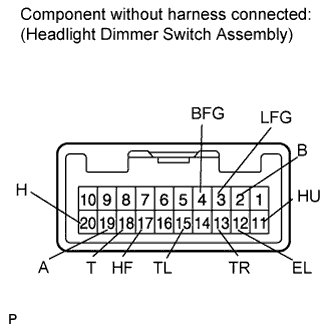
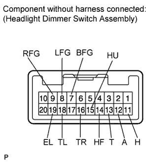
for RHD
-
Remove the headlight dimmer switch assembly Click here.
-
Measure the resistance according to the value(s) in the table below.
Standard Resistance Light Control Switch Tester Connection Switch Condition Specified Condition 19 (EL) - 13 (T) OFF 10 kΩ or higher 13 (T) - 12 (A) OFF 10 kΩ or higher 12 (A) - 11 (H) OFF 10 kΩ or higher 19 (EL) - 13 (T) TAIL Below 1 Ω 19 (EL) - 13 (T) HEAD Below 1 Ω 13 (T) - 11 (H) HEAD Below 1 Ω 19 (EL) - 12 (A) AUTO Below 1 Ω Dimmer Switch Tester Connection Switch Condition Specified Condition 15 (HU) - 19 (EL) LOW BEAM 10 kΩ or higher 15 (HU) - 19 (EL) HIGH BEAM Below 1 Ω 19 (EL) - 14 (HF) HIGH FLASH Below 1 Ω Turn Signal Switch Tester Connection Switch Condition Specified Condition 19 (EL) - 16 (TR) Right turn Below 1 Ω 19 (EL) - 16 (TR) Neutral 10 kΩ or higher 19 (EL) - 18 (TL) Neutral 10 kΩ or higher 19 (EL) - 18 (TL) Left turn Below 1 Ω Front Fog Light Switch Tester Connection Switch Condition Specified Condition 8 (LFG) - 7 (BFG) OFF 10 kΩ or higher 8 (LFG) - 7 (BFG) ON Below 1 Ω Rear Fog Light Switch Tester Connection Switch Condition Specified Condition 9 (RFG) - 8 (LFG) OFF 10 kΩ or higher 9 (RFG) - 8 (LFG) ON Below 1 Ω
-
NG 
REPLACE HEADLIGHT DIMMER SWITCH ASSEMBLY Click here
OK 
-
-
CHECK HARNESS AND CONNECTOR
-
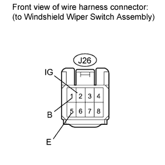
Disconnect the J26 windshield wiper switch assembly connector.
-
Measure the resistance according to the value(s) in the table below.
Standard Resistance Tester Connection Condition Specified Condition J26-5 (E) - Body ground Always Below 1 Ω -
Measure the voltage according to the value(s) in the table below.
Standard Voltage Tester Connection Condition Specified Condition J26-1 (B) - J26-5 (E) Always 11 to 14 V J26-2 (IG) - J26-5 (E) Engine switch on (IG) 11 to 14 V
NG
REPAIR OR REPLACE HARNESS OR CONNECTOR
OK
REPLACE WINDSHIELD WIPER SWITCH ASSEMBLY Click here
-