LIGHTING SYSTEM Headlight (HI-BEAM) Circuit
DESCRIPTION
The front controller receives headlight HI switch information from the combination switch, and turns on the headlights.
WIRING DIAGRAM
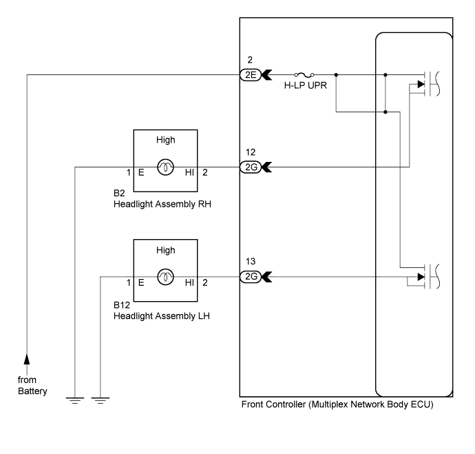
INSPECTION PROCEDURE
PROCEDURE
-
PERFORM ACTIVE TEST USING INTELLIGENT TESTER
-
Connect the intelligent tester to the DLC3.
-
Turn the engine switch on (IG).
-
Turn the intelligent tester on.
-
Enter the following menus: Body / Body No. 5 / Active Test.
-
Check the operation.
Body No. 5 (Front Controller) Tester Display Test Part Control Range Diagnostic Note Light Head (High) Headlight (high) ON/OFF - OK Headlight assembly illuminates.
NG 
INSPECT FUSE (H-LP UPR) Click here
OK 
PROCEED TO NEXT CIRCUIT INSPECTION SHOWN IN PROBLEM SYMPTOMS TABLE Click here
-
-
INSPECT FUSE (H-LP UPR)
-
Remove the H-LP UPR fuse from the No. 2 engine room relay block.
-
Measure the resistance of the fuse.
Standard Resistance Below 1 Ω
NG 
REPLACE FUSE
OK 
-
-
CHECK HARNESS AND CONNECTOR (FRONT CONTROLLER - BATTERY)
-
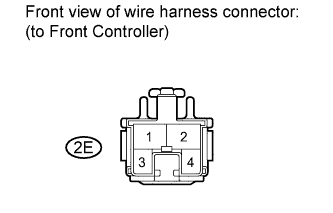
Disconnect the 2E front controller connector.
-
Measure the voltage according to the value(s) in the table below.
Standard Voltage Tester Connection Condition Specified Condition 2E-2 - Body ground Always 11 to 14 V
NG
REPAIR OR REPLACE HARNESS OR CONNECTOR
OK
-
-
CHECK HARNESS AND CONNECTOR (FRONT CONTROLLER - BODY GROUND)
-
Check the wire harness between the headlight LH and front controller, and the headlight LH and body ground.
-
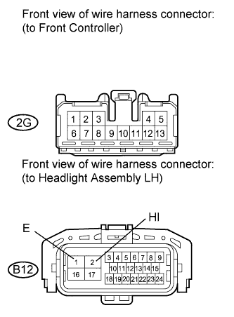
Disconnect the 2G front controller connector.
-
Disconnect the B12 headlight LH connector.
-
Measure the resistance according to the value(s) in the table below.
Standard Resistance Tester Connection Condition Specified Condition 2G-13 - B12-2 (HI) Always Below 1 Ω 2G-13 or B12-2 (HI) - Body ground Always 10 kΩ or higher B12-1 (E) - Body ground Always Below 1 Ω
-
-
Check the wire harness between the headlight RH and front controller, and the headlight RH and body ground.
-
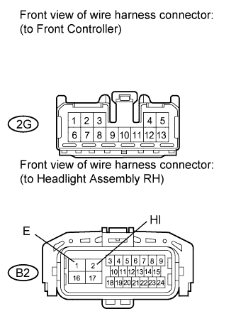
Disconnect the 2G front controller connector.
-
Disconnect the B2 headlight RH connector.
-
Measure the resistance according to the value(s) in the table below.
Standard Resistance Tester Connection Condition Specified Condition 2G-12 - B2-2 (HI) Always Below 1 Ω 2G-12 or B2-2 (HI) - Body ground Always 10 kΩ or higher B2-1 (E) - Body ground Always Below 1 Ω
-
NG
REPAIR OR REPLACE HARNESS OR CONNECTOR
OK
REPLACE FRONT CONTROLLER (MULTIPLEX NETWORK BODY ECU)
-