LIGHTING SYSTEM Daytime Running Light Relay Circuit
DESCRIPTION
The front controller controls the daytime running light system using a built-in IC relay.
The system illuminates the high-intensity LED parking lights (high-intensity circuit).
WIRING DIAGRAM
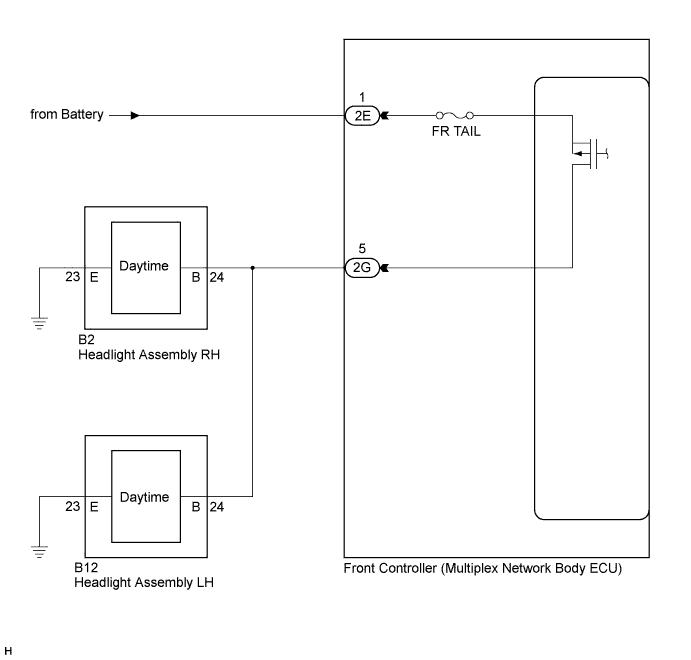
INSPECTION PROCEDURE
PROCEDURE
-
PERFORM ACTIVE TEST USING INTELLIGENT TESTER
-
Connect the intelligent tester to the DLC3.
-
Turn the engine switch on (IG).
-
Turn the intelligent tester on.
-
Enter the following menus: Body Electrical / Body No.5 / Active Test.
-
Check that the daytime running lights operate.
Body No. 5 (Front Controller) Tester Display Test Part Control Range Diagnostic Note Light Head HI DRL Operation High-intensity LED parking lights ON/OFF - OK Daytime running lights illuminate. (LED parking lights illuminate on high-intensity (bright) setting.)
NG 
CHECK HARNESS AND CONNECTOR (FRONT CONTROLLER - HEADLIGHTS) Click here
OK 
PROCEED TO NEXT SUSPECTED AREA SHOWN IN PROBLEM SYMPTOMS TABLE Click here
-
-
CHECK HARNESS AND CONNECTOR (FRONT CONTROLLER - HEADLIGHTS)
-
Disconnect the 2G front controller connector.
-
Disconnect the B2 and B12 headlight assembly connectors.
-
Measure the resistance according to the value(s) in the table below.
Standard Resistance Tester Connection Condition Specified Condition B2-24 (B) - 2G-5 Always Below 1 Ω B2-24 (B) - Body ground Always 10 kΩ or higher B12-24 (B) - 2G-5 Always Below 1 Ω B12-24 (B) - Body ground Always 10 kΩ or higher
NG 
REPAIR OR REPLACE HARNESS OR CONNECTOR
OK 
-
-
REPLACE FRONT CONTROLLER (MULTIPLEX NETWORK BODY ECU)
-
Replace the front controller.
-
Check the operation of the daytime running light system.
Tech Tips
Refer to Operation Check.
Result Result Proceed to Daytime running lights illuminate. A Daytime running lights do not illuminate. B
B
REPLACE MAIN BODY ECU RH (COWL SIDE JUNCTION BLOCK RH)
A
END
-