LIGHTING SYSTEM Headlight Relay Circuit
DESCRIPTION
The headlight relay is turned on by operating the headlight switch.
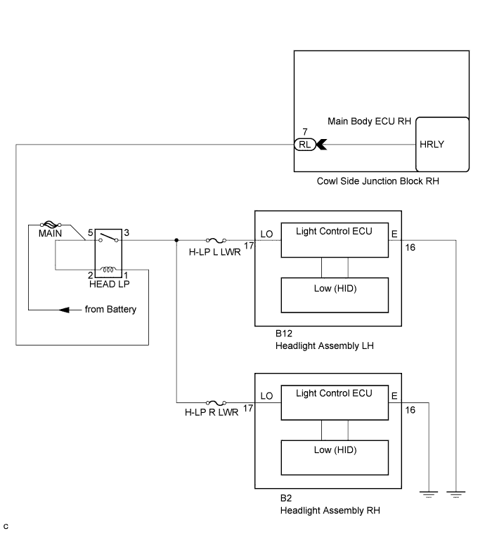
WIRING DIAGRAM
INSPECTION PROCEDURE
PROCEDURE
-
PERFORM ACTIVE TEST USING INTELLIGENT TESTER
-
Connect the intelligent tester to the DLC3.
-
Turn the engine switch on (IG).
-
Turn the intelligent tester on.
-
Enter the following menus: Body / Body / Active Test.
-
Check the operation.
Body (Main Body ECU RH) Tester Display Test Part Control Range Diagnostic Note Headlight Relay Headlight relay ON/OFF - OK Headlight assembly (low) illuminates.
NG 
INSPECT FUSE (H-LP L LWR, H-LP R LWR) Click here
OK 
PROCEED TO NEXT CIRCUIT INSPECTION SHOWN IN PROBLEM SYMPTOMS TABLE Click here
-
-
INSPECT FUSE (H-LP L LWR, H-LP R LWR)
-
Remove the H-LP L LWR fuse from the No. 2 engine room relay block .
-
Remove the H-LP R LWR fuse from the No. 2 engine room relay block .
-
Measure the resistance of the fuses.
Standard Resistance Below 1 Ω
NG 
REPLACE FUSE
OK 
-
-
INSPECT HEAD LP RELAY
-
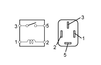
Remove the HEAD LP relay from the engine room No. 1 relay block.
-
Measure the resistance according to the value(s) in the table below.
Standard Resistance Tester Connection Specified Condition 3 - 5 10 kΩ or higher 3 - 5 Below 1 Ω
(When battery voltage is applied to terminals 1 and 2)
NG
REPLACE HEAD LP RELAY
OK
-
-
CHECK HARNESS AND CONNECTOR (MAIN BODY ECU RH - BATTERY)
-
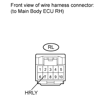
Disconnect the RL main body ECU RH connector.
-
Measure the voltage according to the value(s) in the table below.
Standard Voltage Tester Connection Condition Specified Condition RL-7 (HRLY) - Body ground Always 11 to 14 V
NG
REPAIR OR REPLACE HARNESS OR CONNECTOR
OK
-
-
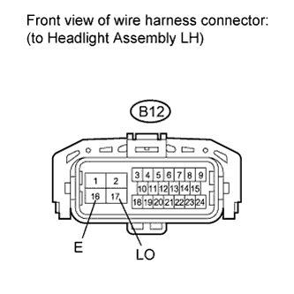
CHECK HARNESS AND CONNECTOR (HEADLIGHT (LOW LH OR LOW RH) - BATTERY AND BODY GROUND)
-
Check the wire harness between the headlight (Low LH) and battery, and the headlight (Low LH) and body ground.
-
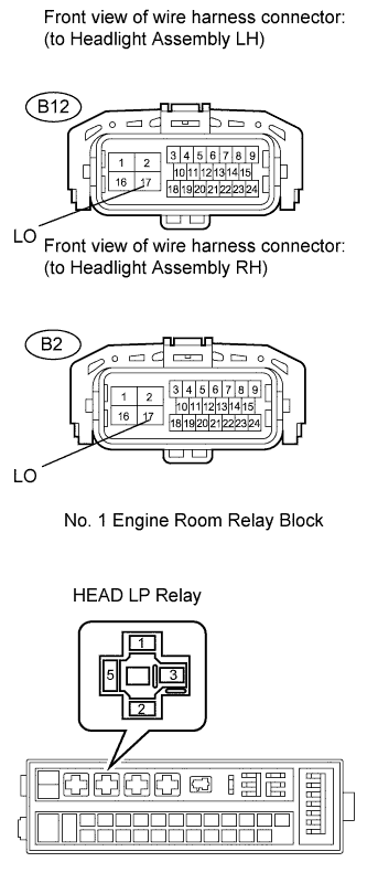
Disconnect the B12 headlight connector.
-
Measure the voltage according to the value(s) in the table below.
Standard Voltage Tester Connection Condition Specified Condition B12-17 (LO) - Body ground Turn the light control switch to the ON (HEAD) position. 11 to 14 V -
Measure the resistance according to the value(s) in the table below.
Standard Resistance Tester Connection Condition Specified Condition B12-16 (E) - Body ground Always Below 1 Ω
-
-
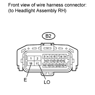
Check the wire harness between the headlight (Low RH) and battery, and the headlight (Low RH) and body ground.
-
Disconnect the B2 headlight connector.
-
Measure the voltage according to the value(s) in the table below.
Standard Voltage Tester Connection Condition Specified Condition B2-17 (LO) - Body ground Turn the light control switch to the ON (HEAD) position. 11 to 14 V -
Measure the resistance according to the value(s) in the table below.
Standard Resistance Tester Connection Condition Specified Condition B2-16 (E) - Body ground Always Below 1 Ω
-
NG
CHECK HARNESS AND CONNECTOR (HEADLIGHT (LOW LH OR LOW RH) - HEAD LP RELAY) Click here
OK
REPLACE HEADLIGHT ASSEMBLY (LOW LH OR LOW RH) Click here
-
-
CHECK HARNESS AND CONNECTOR (HEADLIGHT (LOW LH OR LOW RH) - HEAD LP RELAY)
-
Check the harness and the connectors between the headlight (Low LH or Low RH) and the HEAD LP relay.
-
Disconnect the B12 headlight connector.
-
Remove the HEAD LP relay from the No. 1 engine room relay block.
-
Measure the resistance according to the value(s) in the table below.
Standard Resistance (Check for open) Headlight Assembly Tester Connection Specified Condition LH B12-17 (LO) - HEAD LP relay terminal (3) Below 1 Ω RH B2-17 (LO) - HEAD LP relay terminal (3) Below 1 Ω Standard Resistance (Check for short) Headlight Assembly Tester Connection Specified Condition LH B12-17 (LO) or HEAD LP relay terminal (3) - Body ground 10 kΩ or higher RH B2-17 (LO) or HEAD LP relay terminal (3) - Body ground 10 kΩ or higher
-
NG
REPAIR OR REPLACE HARNESS OR CONNECTOR
OK
REPLACE MAIN BODY ECU RH (COWL SIDE JUNCTION BLOCK RH)
-