LIGHTING SYSTEM, Diagnostic DTC:B2414

| DTC Code | DTC Name |
|---|---|
| B2414 | Steering Position Sensor Malfunction |
DESCRIPTION
The AFS ECU receives signals regarding the swerve-angle from the steering angle sensor in the steering wheel.
| DTC No. | DTC Detection Condition | Trouble Area |
|---|---|---|
| B2414 |
|
|
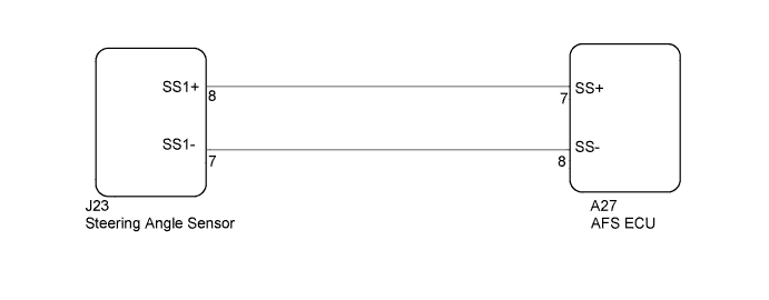
WIRING DIAGRAM
INSPECTION PROCEDURE
PROCEDURE
-
CHECK DTC (VEHICLE STABILITY CONTROL SYSTEM)
-
Check that vehicle stability control system DTC are not output Click here.
Result Result Proceed to DTC (C1231/31) is not output A DTC (C1231/31) is output B
B 
REPAIR CIRCUITS INDICATED BY OUTPUT DTCS Click here
A 
-
-
READ VALUE USING INTELLIGENT TESTER
-
Connect the intelligent tester to the DLC3.
-
Turn the engine switch on (IG).
-
Turn the intelligent tester on.
-
Enter the following menus: Body / AFS / Data List.
-
Read the display on the intelligent tester.
AFS (AFS ECU) Tester Display Measurement Item/Range Normal Condition Diagnostic Note Steer Sens Sig Steering angle sensor signal value / -384° to 382.5° Approx. 0°
(When steering wheel is straight)
- OK Condition sign can be displayed. Result Result Proceed to OK (When checking from Problem Symptoms Table) A OK (When checking from Diagnostic Trouble Code Chart) B NG C
B
REPLACE AFS ECU Click here
C 
CHECK HARNESS AND CONNECTOR (STEERING ANGLE SENSOR - AFS ECU) Click here
A 
PROCEED TO NEXT CIRCUIT INSPECTION SHOWN IN PROBLEM SYMPTOMS TABLE Click here
-
-
CHECK HARNESS AND CONNECTOR (STEERING ANGLE SENSOR - AFS ECU)
-
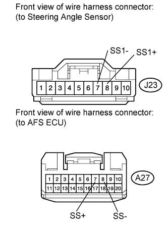
Disconnect the J23 steering angle sensor connector.
-
Disconnect the A27 AFS ECU connector.
-
Measure the resistance according to the value(s) in the table below.
Standard Resistance Tester Connection Condition Specified Condition J23-7 (SS1-) - A27-8 (SS-) Always Below 1 Ω J23-8 (SS1+) - A27-7 (SS+) Always Below 1 Ω A27-8 (SS-) - Body ground Always 10 kΩ or higher A27-7 (SS+) - Body ground Always 10 kΩ or higher
NG
REPAIR OR REPLACE HARNESS OR CONNECTOR
OK
-
-
CHECK AFS ECU
-
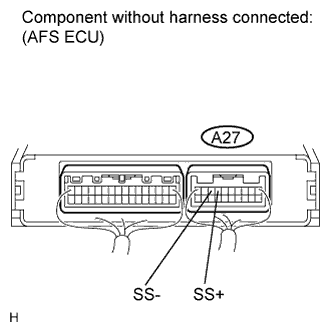
Reconnect the A27 AFS ECU connector.
-
Measure the voltage according to the value(s) in the table below.
Standard Voltage Tester Connection Switch Condition Specified Condition A27-7 (SS+) - A27-8 (SS-) Engine switch on (IG) Approx. 5 V
NG
REPLACE AFS ECU Click here
OK
REPLACE STEERING ANGLE SENSOR Click here
-