LIGHTING SYSTEM, Diagnostic DTC:B2412, B2413

| DTC Code | DTC Name |
|---|---|
| B2412 | Headlight Swivel Motor LH Malfunction |
| B2413 | Headlight Swivel Motor RH Malfunction |
DESCRIPTION
The swivel actuator receives a signal from the AFS ECU to operate and sends a signal regarding the direction of the headlight and condition of the headlight swivel motor to the AFS ECU.
| DTC No. | DTC Detection Condition | Trouble Area |
|---|---|---|
| B2412 |
|
|
| B2413 |
|
|
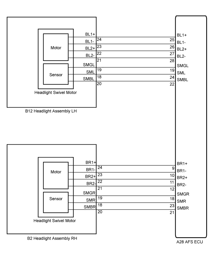
WIRING DIAGRAM
INSPECTION PROCEDURE
PROCEDURE
-
PERFORM ACTIVE TEST USING INTELLIGENT TESTER
-
Connect the intelligent tester to the DLC3.
-
Turn the engine switch on (IG).
-
Turn the intelligent tester on.
-
Enter the following menus: Body / AFS / Active Test.
-
Check the operation.
AFS (AFS ECU) Tester Display Test Part Control Range Diagnostic Note Drive The Swivel Motor RH Swivel motor RH right direction rotation RIGHT/OFF - Drive The Swivel Motor LH Swivel motor LH left direction rotation LEFT/OFF - OK Swivel motor operates. Result Result Proceed to OK (When checking from Problem Symptoms Table) A OK (When checking from Diagnostic Trouble Code Chart) B NG C
B 
REPLACE AFS ECU Click here
C 
INSPECT HEADLIGHT ASSEMBLY Click here
A 
PROCEED TO NEXT CIRCUIT INSPECTION SHOWN IN PROBLEM SYMPTOMS TABLE Click here
-
-
INSPECT HEADLIGHT ASSEMBLY
-
Disconnect the B12 and B2 headlight assembly connectors.
-
Measure the resistance according to the value(s) in the table below.
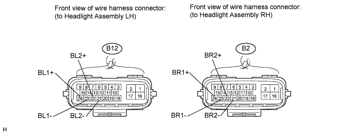
Standard Resistance LH Side (B2412) Tester Connection Condition Specified Condition B12-23 (BL1-) - B12-24 (BL1+) Always 6 to 8 Ω B12-21 (BL2-) - B12-22 (BL2+) Always 6 to 8 Ω RH Side (B2413) Tester Connection Condition Specified Condition B2-23 (BR1-) - B2-24 (BR1+) Always 6 to 8 Ω B2-21 (BR2-) - B2-22 (BR2+) Always 6 to 8 Ω Tech Tips
Measure the resistance after the headlight has cooled.
NG
REPLACE HEADLIGHT ASSEMBLY Click here
OK 
-
-
CHECK HARNESS AND CONNECTOR (HEADLIGHT ASSEMBLY - AFS ECU)
-
Disconnect the A28 AFS ECU connector.
-
Disconnect the B12 and B2 headlight connectors.
-
Measure the resistance according to the value(s) in the table below.
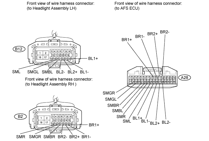
Standard Resistance LH Side (B2412) Tester Connection Condition Specified Condition A28-25 (BL1+) - B12-24 (BL1+) Always Below 1 Ω A28-26 (BL1-) - B12-23 (BL1-) Always Below 1 Ω A28-27 (BL2+)- B12-22 (BL2+) Always Below 1 Ω A28-28 (BL2-) - B12-21 (BL2-) Always Below 1 Ω A28-19 (SMGL) - B12-19 (SMGL) Always Below 1 Ω A28-24 (SML) - B12-18 (SML) Always Below 1 Ω A28-22 (SMBL) - B12-20 (SMBL) Always Below 1 Ω A28-25 (BL1+) - Body ground Always 10 kΩ or higher A28-26 (BL1-) - Body ground Always 10 kΩ or higher A28-27 (BL2+) - Body ground Always 10 kΩ or higher A28-28 (BL2-) - Body ground Always 10 kΩ or higher A28-19 (SMGL) - Body ground Always 10 kΩ or higher A28-24 (SML) - Body ground Always 10 kΩ or higher A28-22 (SMBL) - Body ground Always 10 kΩ or higher RH Side (B2413) Tester Connection Condition Specified Condition A28-9 (BR1+) - B2-24 (BR1+) Always Below 1 Ω A28-10 (BR1-) - B2-23 (BR1-) Always Below 1 Ω A28-11 (BR2+) - B2-22 (BR2+) Always Below 1 Ω A28-12 (BR2-) - B2-21 (BR2-) Always Below 1 Ω A28-18 (SMGR) - B2-19 (SMGR) Always Below 1 Ω A28-21 (SMBR) - B2-20 (SMBR) Always Below 1 Ω A28-23 (SMR) - B2-18 (SMR) Always Below 1 Ω A28-9 (BR1+) - Body ground Always 10 kΩ or higher A28-10 (BR1-) - Body ground Always 10 kΩ or higher A28-11 (BR2+) - Body ground Always 10 kΩ or higher A28-12 (BR2-) - Body ground Always 10 kΩ or higher A28-18 (SMGR) - Body ground Always 10 kΩ or higher A28-21 (SMBR) - Body ground Always 10 kΩ or higher A28-23 (SMR) - Body ground Always 10 kΩ or higher
NG
REPAIR OR REPLACE HARNESS OR CONNECTOR
OK
-
-
CHECK AFS ECU
-
Disconnect the B12 and B2 headlight connectors.
-
Measure the voltage according to the value(s) in the table below.
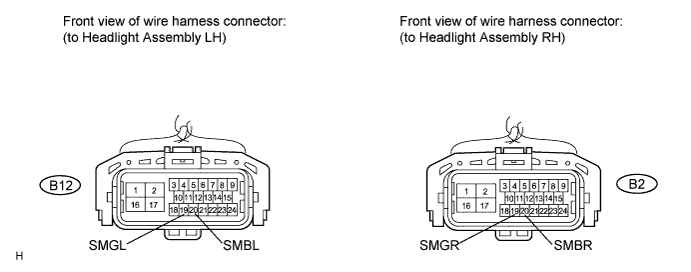
Standard Voltage LH Side (B2412) Tester Connection Condition Specified Condition B12-20 (SMBL) - B12-19 (SMGL) Engine switch off Below 1 V Engine switch on (IG) 4.5 to 5.5 V RH Side (B2413) Tester Connection Condition Specified Condition B2-20 (SMBR) - B2-19 (SMGR) Engine switch off Below 1 V Engine switch on (IG) 4.5 to 5.5 V
NG
REPLACE AFS ECU Click here
OK
-
-
REPLACE HEADLIGHT ASSEMBLY
-
Temporarily replace the headlight assembly with a new or normally functioning one Click here.
-
Check that the headlight assembly operates.
OK Returns to normal operation.
NG
REPLACE AFS ECU Click here
OK
END
-