LIGHTING SYSTEM, Diagnostic DTC:B1244

| DTC Code | DTC Name |
|---|---|
| B1244 | Light Sensor Circuit Malfunction |
DESCRIPTION
This DTC is output when a failure of the automatic light control sensor circuit is detected.
| DTC No. | DTC Detection Condition | Trouble Area |
|---|---|---|
| B1244 |
|
|
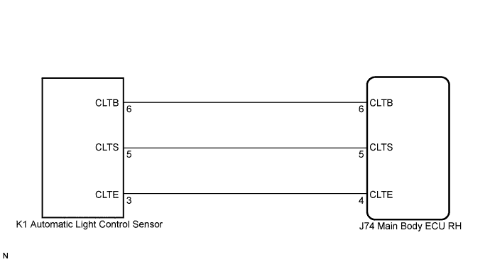
WIRING DIAGRAM
INSPECTION PROCEDURE
PROCEDURE
-
READ VALUE USING INTELLIGENT TESTER
-
Connect the intelligent tester to the DLC3.
-
Turn the engine switch on (IG).
-
Turn the intelligent tester on.
-
Enter the following menus: Body / Body / Data List.
-
Read the display on the intelligent tester.
Body (Main Body ECU RH) Tester Display Measurement Item/Range Normal Condition Diagnostic Note Illumination Rate Info Illumination information / 0 to 99.99 ms. 0.8 to 22 ms. - -
The value of the illumination rate should change in the following range when light shines on the automatic light control sensor or when the automatic light control sensor is covered.
OK 0.8 to 22 ms. Tech Tips
This is the time taken for the automatic light control sensor to generate one cycle of frequency according to the brightness.
OK 
REPLACE MAIN BODY ECU RH (COWL SIDE JUNCTION BLOCK RH)
NG 
-
-
CHECK HARNESS AND CONNECTOR (MAIN BODY ECU RH - AUTOMATIC LIGHT CONTROL SENSOR)
-
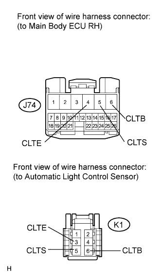
Disconnect the J74 main body ECU RH connector.
-
Disconnect the K1 automatic light control sensor connector.
-
Measure the resistance according to the value(s) in the table below.
Standard Resistance Tester Connection Condition Specified Condition J74-6 (CLTB) - K1-6 (CLTB) Always Below 1 Ω J74-5 (CLTS) - K1-5 (CLTS) Always Below 1 Ω J74-4 (CLTE) - K1-3 (CLTE) Always Below 1 Ω J74-6 (CLTB) - Body ground Always 10 kΩ or higher J74-5 (CLTS) - Body ground Always 10 kΩ or higher J74-4 (CLTE) - Body ground Always 10 kΩ or higher -
Connect the 2 connectors.
NG
REPAIR OR REPLACE HARNESS OR CONNECTOR
OK
-
-
CHECK AUTOMATIC LIGHT CONTROL SENSOR
-
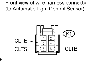
Disconnect the automatic light control sensor.
-
Measure the resistance according to the value(s) in the table below.
Standard Resistance Tester Connection Condition Specified Condition K1-3 (CLTE) - Body ground Always Below 1 Ω -
Connect the voltmeter's positive (+) lead to terminal 6 and the negative (-) lead to terminal 3.
-
Measure the voltage according to the value(s) in the table below.
Standard Voltage Tester Connection Condition Specified Condition K1-3 (CLTE) - K1-6 (CLTB) Engine switch on (IG) 11 to 14 V -
Connect the K1 automatic light control sensor connector.
-
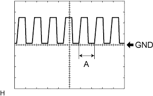
Connect the oscilloscope and check the waveform according to the table below.
Standard Voltage Tester Connection Condition Specified Condition Tester Range K1-3 (CLTE) - K1-5 (CLTS) Engine switch on (IG), Headlight dimmer switch in AUTO Correct waveform is as shown in the illustration 5 V/Division, 5 msec/Division If the ambient light becomes brighter, width A becomes narrower.
NG
REPLACE AUTOMATIC LIGHT CONTROL SENSOR Click here
OK 
REPLACE MAIN BODY ECU RH (COWL SIDE JUNCTION BLOCK RH)
-