LIGHTING SYSTEM, Diagnostic DTC:B2416

| DTC Code | DTC Name |
|---|---|
| B2416 | Height Control Sensor Malfunction |
DESCRIPTION
The AFS ECU receives signals regarding the height of the front/rear of the vehicle from the height control sensor.
| DTC No. | DTC Detection Condition | Trouble Area |
|---|---|---|
| B2416 |
|
|
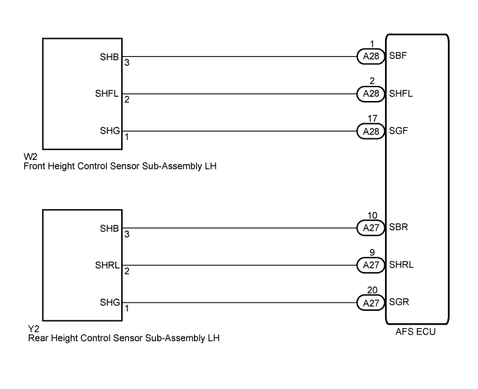
WIRING DIAGRAM
INSPECTION PROCEDURE
PROCEDURE
-
READ VALUE USING INTELLIGENT TESTER
-
Connect the intelligent tester to the DLC3.
-
Turn the engine switch on (IG).
-
Turn the intelligent tester on.
-
Enter the following menus: Body / AFS / Data List.
-
Read the display on the intelligent tester.
AFS (AFS ECU) Tester Display Measurement Item/Range Normal Condition Diagnostic Note Fr Height Sens Front height sensor signal value / 0 to 5 V Approx. 2.5 V - Rr Height Sens Rear height sensor signal value / 0 to 5 V Approx. 2.5 V - OK Condition sign can be displayed. Result Result Proceed to OK (When checking from Problem Symptoms Table) A OK (When checking from Diagnostic Trouble Code Chart B NG C
B 
REPLACE AFS ECU Click here
C 
CHECK HARNESS AND CONNECTOR (FRONT HEIGHT CONTROL SENSOR SUB-ASSEMBLY LH CIRCUIT) Click here
A 
PROCEED TO NEXT CIRCUIT INSPECTION SHOWN IN PROBLEM SYMPTOMS TABLE Click here
-
-
CHECK HARNESS AND CONNECTOR (FRONT HEIGHT CONTROL SENSOR SUB-ASSEMBLY LH CIRCUIT)
-
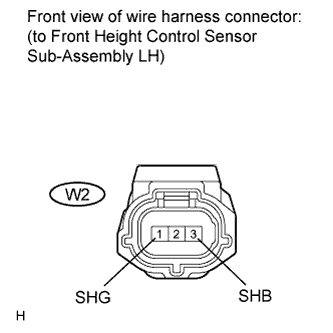
Disconnect the W2 front height control sensor sub-assembly LH connector.
-
Measure the voltage according to the value(s) in the table below.
Standard Voltage Tester Connection Switch Condition Specified Condition W2-1 (SHG) - W2-3 (SHB) Engine switch on (IG) 4.5 to 5.5 V
NG
CHECK HARNESS AND CONNECTOR (AFS ECU - FRONT HEIGHT CONTROL SENSOR SUB-ASSEMBLY LH) Click here
OK 
-
-
CHECK HARNESS AND CONNECTOR (REAR HEIGHT CONTROL SENSOR SUB-ASSEMBLY LH CIRCUIT)
-
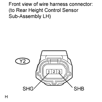
Disconnect the Y2 rear height control sensor sub-assembly LH connector.
-
Measure the voltage according to the value(s) in the table below.
Standard Voltage Tester Connection Switch Condition Specified Condition Y2-1 (SHG) - Y2-3 (SHB) Engine switch on (IG) 4.5 to 5.5 V
NG
CHECK HARNESS AND CONNECTOR (AFS ECU - REAR HEIGHT CONTROL SENSOR SUB-ASSEMBLY LH) Click here
OK
-
-
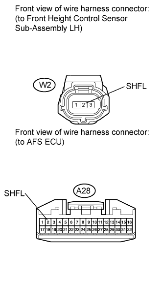
CHECK HARNESS AND CONNECTOR (AFS ECU - FRONT HEIGHT CONTROL SENSOR SUB-ASSEMBLY LH)
-
Disconnect the A28 AFS ECU connector.
-
Measure the resistance according to the value(s) in the table below.
Standard Resistance Tester Connection Condition Specified Condition A28-2 (SHFL) - W2-2 (SHFL) Always Below 1 Ω A28-2 (SHFL) - Body ground Always 10 kΩ or higher
NG
REPAIR OR REPLACE HARNESS OR CONNECTOR
OK
-
-
CHECK HARNESS AND CONNECTOR (AFS ECU - REAR HEIGHT CONTROL SENSOR SUB-ASSEMBLY LH)
-
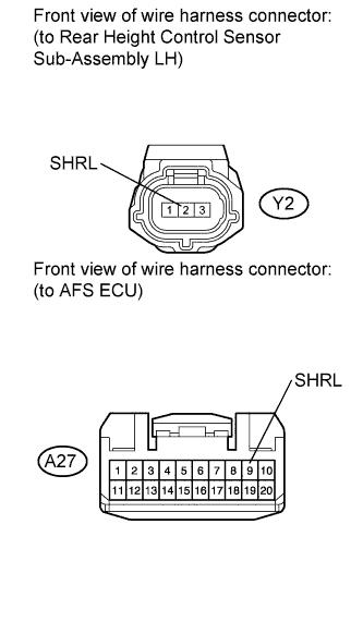
Disconnect the Y2 rear height control sensor sub-assembly LH connector.
-
Disconnect the A27 AFS ECU connector.
-
Measure the resistance according to the value(s) in the table below.
Standard Resistance Tester Connection Condition Specified Condition A27-9 (SHRL) - Y2-2 (SHRL) Always Below 1 Ω A27-9 (SHRL) - Body ground Always 10 kΩ or higher
NG
REPAIR OR REPLACE HARNESS OR CONNECTOR
OK
-
-
INSPECT FRONT HEIGHT CONTROL SENSOR SUB-ASSEMBLY LH
-
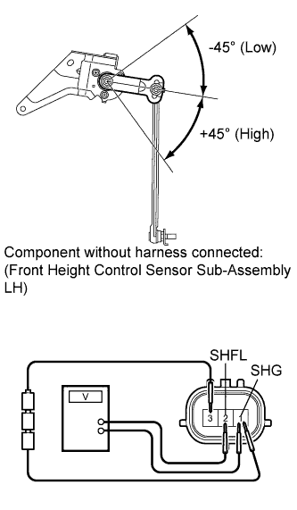
Connect 3 dry cell batteries (1.5 V) in series.
-
Remove the front height control sensor sub-assembly LH.
-
Connect the positive (+) lead from the battery to terminal 3 and the negative (-) lead from the battery to terminal 1.
-
Measure the voltage between terminals 2 and 1 while slowly moving the link up and down.
Standard Voltage Tester Connection Condition Specified Condition W2-2 (SHFL) - W2-1 (SHG) +45° Approx. 4.5 V W2-2 (SHFL) - W2-1 (SHG) 0° (Normal) Approx. 2.5 V W2-2 (SHFL) - W2-1 (SHG) -45° (Low) Approx. 0.5 V
NG
REPLACE FRONT HEIGHT CONTROL SENSOR SUB-ASSEMBLY LH Click here
OK
-
-
INSPECT REAR HEIGHT CONTROL SENSOR SUB-ASSEMBLY LH
-
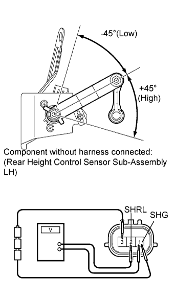
Connect 3 dry cell batteries (1.5 V) in series.
-
Remove the rear height control sensor sub-assembly LH.
-
Connect the positive (+) lead from the battery to terminal 3 and the negative (-) lead from the battery to terminal 1.
-
Measure the voltage between terminals 2 and 1 while slowly moving the link up and down.
Standard Voltage Tester Connection Condition Specified Condition Y2-2 (SHRL) - Y2-1 (SHG) +45° Approx. 4.5 V Y2-2 (SHRL) - Y2-1 (SHG) 0° (Normal) Approx. 2.5 V Y2-2 (SHRL) - Y2-1 (SHG) -45° (Low) Approx. 0.5 V
NG
REPLACE REAR HEIGHT CONTROL SENSOR SUB-ASSEMBLY LH Click here
OK
REPLACE AFS ECU Click here
-
-
CHECK HARNESS AND CONNECTOR (AFS ECU - FRONT HEIGHT CONTROL SENSOR SUB-ASSEMBLY LH)
-
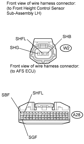
Disconnect the W2 front height control sensor sub-assembly LH connector.
-
Disconnect the A28 AFS ECU connector.
-
Measure the resistance according to the value(s) in the table below.
Standard Resistance Tester Connection Condition Specified Condition A28-1 (SBF) - W2-3 (SHB) Always Below 1 Ω A28-2 (SHFL) - W2-2 (SHFL) Always Below 1 Ω A28-17 (SGF) - W2-1 (SHG) Always Below 1 Ω A28-1 (SBF) - Body ground Always 10 kΩ or higher A28-2 (SHFL) - Body ground Always 10 kΩ or higher A28-17 (SGF) - Body ground Always 10 kΩ or higher
NG
REPAIR OR REPLACE HARNESS OR CONNECTOR (AFS ECU - FRONT HEIGHT CONTROL SENSOR SUB-ASSEMBLY LH)
OK
REPLACE AFS ECU Click here
-
-
CHECK HARNESS AND CONNECTOR (AFS ECU - REAR HEIGHT CONTROL SENSOR SUB-ASSEMBLY LH)
-
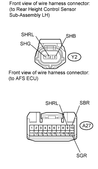
Disconnect the Y2 rear height control sensor sub-assembly LH connector.
-
Disconnect the A27 AFS ECU connector.
-
Measure the resistance according to the value(s) in the table below.
Standard Resistance Tester Connection Condition Specified Condition A27-10 (SBR) - Y2-3 (SHB) Always Below 1 Ω A27-9 (SHRL) - Y2-2 (SHRL) Always Below 1 Ω A27-20 (SGR) - Y2-1 (SHG) Always Below 1 Ω A27-10 (SBR) - Body ground Always 10 kΩ or higher A27-9 (SHRL) - Body ground Always 10 kΩ or higher A27-20 (SGR) - Body ground Always 10 kΩ or higher
NG
REPAIR OR REPLACE HARNESS OR CONNECTOR (AFS ECU - REAR HEIGHT CONTROL SENSOR SUB-ASSEMBLY LH)
OK
REPLACE AFS ECU Click here
-