WIPER AND WASHER SYSTEM Washer Fluid Level Warning Switch Circuit
DESCRIPTION
The front controller receives washer fluid level warning switch condition (on or off) information, and sends it through multiplex communication lines to the combination meter.
The combination meter receives this information, and turns on the washer fluid level warning light when the washer fluid level becomes low.
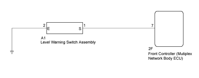
WIRING DIAGRAM
INSPECTION PROCEDURE
PROCEDURE
-
READ VALUE USING INTELLIGENT TESTER
-
Connect the intelligent tester to the DLC3.
-
Turn the engine switch on (IG).
-
Turn the intelligent tester on.
-
Enter the following menus: Body / Body No. 5 / Data List.
-
Read the display on the intelligent tester.
Body No. 5 (Front Controller) Tester Display Measurement Item/Range Normal Condition Diagnostic Note Washer Level Switch Washer fluid level switch / ON or OFF ON: Washer jar is empty
OFF: Washer jar is full
-
NG 
INSPECT LEVEL WARNING SWITCH ASSEMBLY Click here
OK 
PROCEED TO NEXT CIRCUIT INSPECTION SHOWN IN PROBLEM SYMPTOMS TABLE Click here
-
-
INSPECT LEVEL WARNING SWITCH ASSEMBLY
Tech Tips
The following check should be performed with level warning switch assembly installed to the washer jar.
-
Fill the washer jar with washer fluid.
-
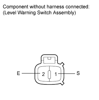
Measure the resistance according to the value(s) in the table below.
Standard Resistance Tester Connection Condition Specified Condition 1 (S) - 2 (E) Fluid volume is more than 700 to 900 ml 10 kΩ or higher 1 (S) - 2 (E) Fluid volume is less than 700 to 900 ml Below 1 Ω
NG 
REPLACE LEVEL WARNING SWITCH ASSEMBLY Click here
OK 
-
-
CHECK HARNESS AND CONNECTOR (LEVEL WARNING SWITCH - FRONT CONTROLLER AND BODY GROUND)
-
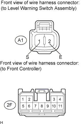
Disconnect the A1 level warning switch assembly connector.
-
Disconnect the 2F front controller connector.
-
Measure the resistance according to the value(s) in the table below.
Standard Resistance Tester Connection Condition Specified Condition 2F-7 - A1-1 (S) Always Below 1 Ω A1-2 (E) - Body ground Always Below 1 Ω 2F-7 - Body ground Always 10 kΩ or higher
NG
REPAIR OR REPLACE HARNESS OR CONNECTOR
OK
REPLACE FRONT CONTROLLER (MULTIPLEX NETWORK BODY ECU)
-