WIPER AND WASHER SYSTEM Washer Motor Circuit
DESCRIPTION
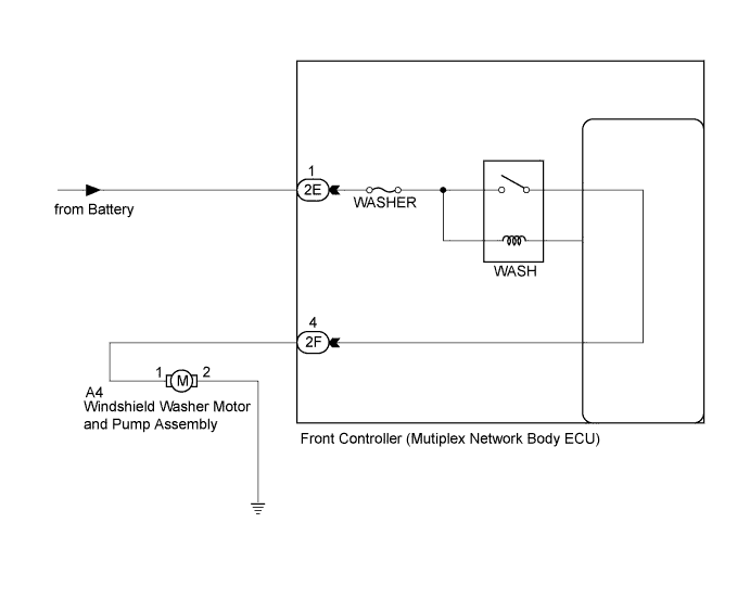
The front controller receives washer switch condition (on or off) information from the windshield wiper switch assembly, and operates the WASH relay.
WIRING DIAGRAM
INSPECTION PROCEDURE
PROCEDURE
-
PERFORM ACTIVE TEST USING INTELLIGENT TESTER
-
Connect the intelligent tester to the DLC3.
-
Turn the engine switch on (IG).
-
Turn the intelligent tester on.
-
Enter the following menus: Body / Body No. 5 / Active Test.
-
Check the operation.
Body No. 5 (Front Controller) Tester Display Test Part Control Range Diagnostic Note Washer Motor Operation Washer motor OFF/ON - OK Washer motor operates.
NG 
INSPECT WINDSHIELD WASHER MOTOR AND PUMP ASSEMBLY Click here
OK 
PROCEED TO NEXT CIRCUIT INSPECTION SHOWN IN PROBLEM SYMPTOMS TABLE Click here
-
-
INSPECT WINDSHIELD WASHER MOTOR AND PUMP ASSEMBLY
Tech Tips
The following check should be performed with the windshield washer motor and pump assembly installed to the washer jar.
-
Fill the washer jar with washer fluid.
-
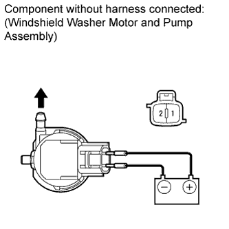
Connect a positive (+) battery lead to terminal 1 of the washer motor, and a negative (-) battery lead to terminal 2.
-
Check that washer fluid flows from the washer jar.
OK Washer fluid is pumped from the washer jar.
NG 
REPLACE WINDSHIELD WASHER MOTOR AND PUMP ASSEMBLY Click here
OK 
-
-
CHECK HARNESS AND CONNECTOR (WINDSHIELD WASHER MOTOR AND PUMP ASSEMBLY - BODY GROUND)
-
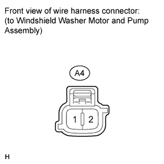
Disconnect the A4 windshield washer motor and pump assembly connector.
-
Measure the resistance according to the value(s) in the table below.
Standard Resistance Tester Connection Condition Specified Condition A4-2 - Body ground Always Below 1 Ω
NG
REPAIR OR REPLACE HARNESS OR CONNECTOR
OK
-
-
CHECK HARNESS OR CONNECTOR (FRONT CONTROLLER - WINDSHIELD WIPER MOTOR AND PUMP ASSEMBLY)
-
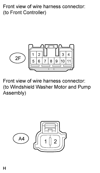
Disconnect the 2F front controller connector.
-
Measure the resistance according to the value(s) in the table below.
Standard Resistance Tester Connection Condition Specified Condition A4-1 - 2F-4 Always Below 1 Ω A4-1 - Body ground Always 10 kΩ or higher
NG
REPAIR OR REPLACE HARNESS OR CONNECTOR
OK
-
-
CHECK HARNESS AND CONNECTOR (BATTERY - FRONT CONTROLLER)
-
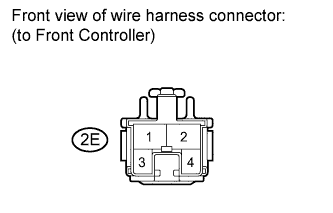
Disconnect the 2E front controller connector.
-
Measure the voltage according to the value(s) in the table below.
Standard Voltage Tester Connection Condition Specified Condition 2E-1 - Body ground Always 11 to 14 V
NG
REPAIR OR REPLACE HARNESS OR CONNECTOR
OK
REPLACE FRONT CONTROLLER (MULTIPLEX NETWORK BODY ECU)
-