WIPER AND WASHER SYSTEM Headlight Cleaner Switch Circuit
DESCRIPTION
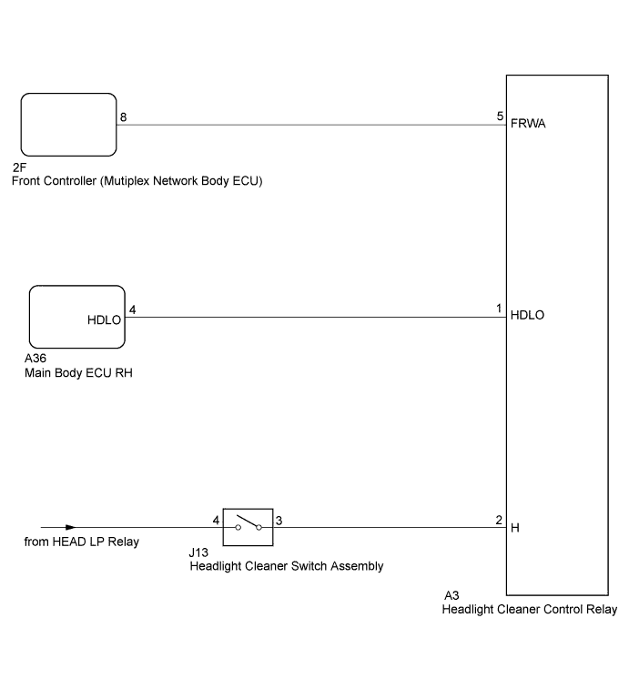
This circuit detects the conditions (on or off) of the headlight cleaner switch.
The headlight cleaner control relay receives the following signals:
-
Headlight cleaner switch signal
-
Headlight operating signal
-
Daytime running light operating signal
-
Front washer motor operating signal
WIRING DIAGRAM
INSPECTION PROCEDURE
PROCEDURE
-
INSPECT HEADLIGHT CLEANER CONTROL RELAY (H SIGNAL)
-
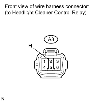
Disconnect the A3 headlight cleaner control relay connector.
-
Measure the voltage according to the value(s) in the table below.
Standard Voltage Tester Connection Switch Condition Specified Condition A3-2 (H) - Body ground Light control switch in HEAD and headlight cleaner switch ON 11 to 14 V A3-2 (H) - Body ground Headlight cleaner switch OFF Below 1 V
NG 
INSPECT HEADLIGHT CLEANER SWITCH ASSEMBLY Click here
OK 
-
-
INSPECT HEADLIGHT CLEANER CONTROL RELAY (FRWA SIGNAL)
-
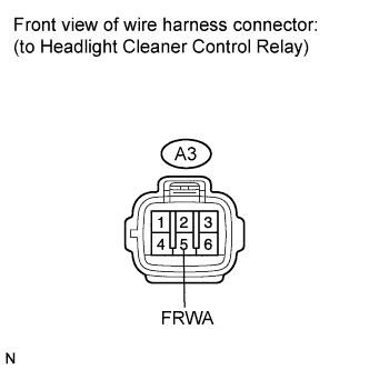
Measure the voltage according to the value(s) in the table below.
Standard Voltage Tester Connection Switch Condition Specified Condition A3-5 (FRWA) - Body ground Engine switch on (IG) and front washer switch OFF 11 to 14 V A3-5 (FRWA) - Body ground Engine switch on (IG) and front washer switch ON Below 1 V
NG
CHECK HARNESS AND CONNECTOR (HEADLIGHT CLEANER CONTROL RELAY - FRONT CONTROLLER) Click here
OK
-
-
INSPECT HEADLIGHT CLEANER CONTROL RELAY (HDLO SIGNAL)
-
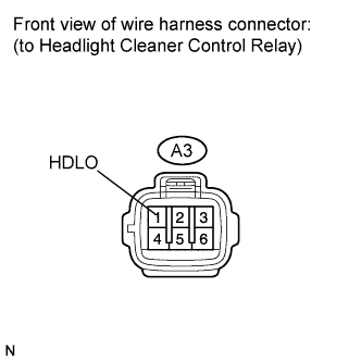
Measure the voltage according to the value(s) in the table below.
Standard Voltage Tester Connection Switch Condition Specified Condition A3-1 (HDLO) - Body ground Light control switch off 11 to 14 V A3-1 (HDLO) - Body ground Light control switch in HEAD Below 1 V
NG
CHECK HARNESS AND CONNECTOR (HEADLIGHT CLEANER CONTROL RELAY - MAIN BODY ECU RH) Click here
OK 
PROCEED TO NEXT CIRCUIT INSPECTION SHOWN IN PROBLEM SYMPTOMS TABLE Click here
-
-
INSPECT HEADLIGHT CLEANER SWITCH ASSEMBLY
-
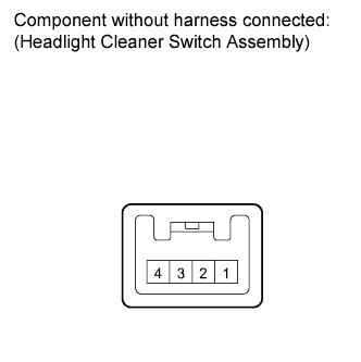
Remove the headlight cleaner switch assembly Click here.
-
Measure the resistance according to the value(s) in the table below.
Standard Resistance Tester Connection Switch Condition Specified Condition 4 - 3 Headlight cleaner switch OFF 10 kΩ or higher 4 - 3 Headlight cleaner switch ON Below 1 Ω
NG 
REPLACE HEADLIGHT CLEANER SWITCH ASSEMBLY Click here
OK
REPAIR OR REPLACE HARNESS OR CONNECTOR (HEAD LP RELAY - HEADLIGHT CLEANER CONTROL RELAY)
-
-
CHECK HARNESS AND CONNECTOR (HEADLIGHT CLEANER CONTROL RELAY - FRONT CONTROLLER)
-
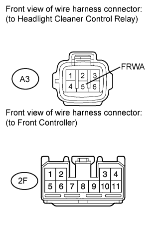
Disconnect the 2F front controller connector.
-
Measure the resistance according to the value(s) in the table below.
Standard Resistance Tester Connection Condition Specified Condition A3-5 (FRWA) - 2F-8 Always Below 1 Ω A3-5 (FRWA) - Body ground Always 10 kΩ or higher
NG
REPAIR OR REPLACE HARNESS OR CONNECTOR
OK
REPLACE FRONT CONTROLLER (MULTIPLEX NETWORK BODY ECU)
-
-
CHECK HARNESS AND CONNECTOR (HEADLIGHT CLEANER CONTROL RELAY - MAIN BODY ECU RH)
-
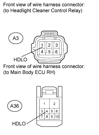
Disconnect the A36 main body ECU RH (cowl side junction block RH) connector.
-
Measure the resistance according to the value(s) in the table below.
Standard Resistance Tester Connector Condition Specified Condition A3-1 (HDLO) - A36-4 (HDLO) Always Below 1 Ω A3-1 (HDLO) - Body ground Always 10 kΩ or higher
NG
REPAIR OR REPLACE HARNESS OR CONNECTOR
OK
REPAIR OR REPLACE MAIN BODY ECU RH (COWL SIDE JUNCTION BLOCK RH)
-