WIPER AND WASHER SYSTEM Wiper Motor Power Source Circuit
DESCRIPTION
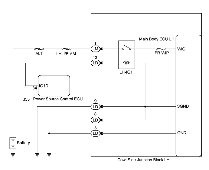
This circuit provides power to the front wiper motor and operates the main body ECU LH (cowl side junction block LH).
WIRING DIAGRAM
INSPECTION PROCEDURE
PROCEDURE
-
CHECK MAIN BODY ECU LH (COWL SIDE JUNCTION BLOCK LH)
-
Measure the voltage according to the value(s) in the table below.
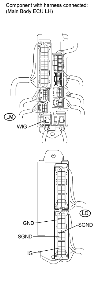
Standard Voltage Tester Connection Condition Specified Condition LD-13 (IG) - LD-8 (SGND) Engine switch off Below 1 V Engine switch on (IG) 11 to 14 V LD-13 (IG) - LD-9 (SGND) Engine switch off Below 1 V Engine switch on (IG) 11 to 14 V LM-1 (WIG) - LD-3 (GND) Always 11 to 14 V
NG 
CHECK HARNESS AND CONNECTOR (MAIN BODY ECU LH - BODY GROUND) Click here
OK 
PROCEED TO NEXT CIRCUIT INSPECTION SHOWN IN PROBLEM SYMPTOMS TABLE Click here
-
-
CHECK HARNESS AND CONNECTOR (MAIN BODY ECU LH - BODY GROUND)
-
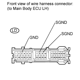
Disconnect the LD connector from the main body ECU LH (cowl side junction block LH).
-
Measure the resistance according to the value(s) in the table below.
Standard Resistance Tester Connection Condition Specified Condition LD-3 (GND) - Body ground Always Below 1 Ω LD-9 (SGND) - Body ground Always Below 1 Ω LD-8 (SGND) - Body ground Always Below 1 Ω
NG 
REPAIR OR REPLACE HARNESS OR CONNECTOR
OK 
-
-
CHECK HARNESS AND CONNECTOR (MAIN BODY ECU LH - BATTERY)
-
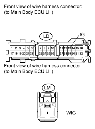
Disconnect the LM connector from the main body ECU LH (cowl side junction block LH).
-
Measure the voltage according to the value(s) in the table below.
Standard Voltage Tester Connection Condition Specified Condition LD-13 (IG) - Body ground Engine switch off Below 1 V Engine switch on (IG) 11 to 14 V LM-1 (WIG) - Body ground Always 11 to 14 V
NG
REPAIR OR REPLACE HARNESS OR CONNECTOR
OK
PROCEED TO NEXT CIRCUIT INSPECTION SHOWN IN PROBLEM SYMPTOMS TABLE Click here
-