OUTER REAR VIEW MIRROR INSPECTION

-
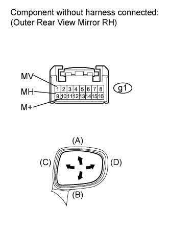
INSPECT OUTER REAR VIEW MIRROR ASSEMBLY RH
-
Inspect outer mirror motor operation.
-
Apply battery voltage and check the operation of the mirror face, as shown in the table and illustration.
Standard Measurement Condition Specified Condition Battery positive (+) → Terminal 1 (MV)
Battery negative (-) → Terminal 10 (M+)
Turns upward (A) Battery positive (+) → Terminal 10 (M+)
Battery negative (-) → Terminal 1 (MV)
Turns downward (B) Battery positive (+) → Terminal 9 (MH)
Battery negative (-) → Terminal 10 (M+)
Turns left (C) Battery positive (+) → Terminal 10 (M+)
Battery negative (-) → Terminal 9 (MH)
Turns right (D) If the result is not as specified, replace the mirror assembly.
-
-
Inspect outer mirror heater operation.
-
Apply battery voltage and check the operation of the mirror face, as shown in the table below.
Standard Measurement Condition Specified Condition Battery positive (+) → Terminal 3 (+)
Battery negative (-) → Terminal 9 (-)
Mirror surface temperature becomes higher If the result is not as specified, replace the mirror assembly.
-
-
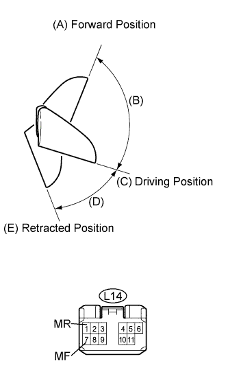
Inspect outer mirror retractable operation.
-
Apply battery voltage and check the operation of the mirror face, as shown in the table and illustration.
Standard Measurement Condition Mirror Position Specified Condition Battery positive (+) → Terminal 1 (MR)
Battery negative (-) → Terminal 7 (MF)
Forward position (A) Moves from (A) to retracted position (E) Battery negative (-) → Terminal 1 (MR)
Battery positive (+) → Terminal 7 (MF)
Forward position (A) Does not move Battery positive (+) → Terminal 1 (MR)
Battery negative (-) → Terminal 7 (MF)
Position between forward position (A) and driving position (C) Moves from (B) to forward position (A) Battery negative (-) → Terminal 1 (MR)
Battery positive (+) → Terminal 7 (MF)
Position between forward position (A) and driving position (C) Moves from (B) to forward position (A) Battery positive (+) → Terminal 1 (MR)
Battery negative (-) → Terminal 7 (MF)
Driving position (C) Moves from (C) to retracted position (E) Battery negative (-) → Terminal 1 (MR)
Battery positive (+) → Terminal 7 (MF)
Driving position (C) Does not move Battery positive (+) → Terminal 1 (MR)
Battery negative (-) → Terminal 7 (MF)
Position between driving position (C) and retracted position (E) Moves from (D) to retracted position (E) Battery negative (-) → Terminal 1 (MR)
Battery positive (+) → Terminal 7 (MF)
Position between driving position (C) and retracted position (E) Moves from (D) to driving position (C) Battery positive (+) → Terminal 1 (MR)
Battery negative (-) → Terminal 7 (MF)
Retracted position (E) Does not move Battery negative (-) → Terminal 1 (MR)
Battery positive (+) → Terminal 7 (MF)
Retracted position (E) Moves from (E) to driving position (C) Note
-
Disconnect and reconnect the battery between each mirror position check.
-
Do not apply battery voltage when moving the mirror by hand into each mirror position.
If the result is not as specified, replace the mirror assembly.
-
-
-
-
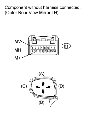
INSPECT OUTER REAR VIEW MIRROR ASSEMBLY LH
-
Inspect outer mirror motor operation.
-
Remove the outer rear view mirror assembly.
-
Apply battery voltage and check the operation of the mirror face, as shown in the table and illustration.
Standard Measurement Condition Specified Condition Battery positive (+) → Terminal 1 (MV)
Battery negative (-) → Terminal 10 (M+)
Turns upward (A) Battery positive (+) → Terminal 10 (M+)
Battery negative (-) → Terminal 1 (MV)
Turns downward (B) Battery positive (+) → Terminal 9 (LMHR)
Battery negative (-) → Terminal 10 (LM+R)
Turns left (C) Battery positive (+) → Terminal 10 (M+)
Battery negative (-) → Terminal 9 (MH)
Turns right (D) If the result is not as specified, replace the mirror assembly.
-
-
Inspect outer mirror heater operation.
-
Apply battery voltage and check the operation of the mirror face, as shown in the table below.
Standard Measurement Condition Specified Condition Battery positive (+) → Terminal 3 (HTR+)
Battery negative (-) → Terminal 9 (HTR-)
Mirror surface temperature becomes higher If the result is not as specified, replace the mirror assembly.
-
-
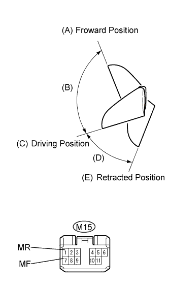
Inspect outer mirror retractable operation.
-
Apply battery voltage and check the operation of the mirror face, as shown in the table and illustration.
Standard Measurement Condition Mirror Position Specified Condition Battery positive (+) → Terminal 1 (MR)
Battery negative (-) → Terminal 7 (MF)
Forward position (A) Moves from (A) to retracted position (E) Battery negative (-) → Terminal 1 (MR)
Battery positive (+) → Terminal 7 (MF)
Forward position (A) Does not move Battery positive (+) → Terminal 1 (MR)
Battery negative (-) → Terminal 7 (MF)
Position between forward position (A) and driving position (C) Moves from (B) to forward position (A) Battery negative (-) → Terminal 1 (MR)
Battery positive (+) → Terminal 7 (MF)
Position between forward position (A) and driving position (C) Moves from (B) to forward position (A) Battery positive (+) → Terminal 1 (MR)
Battery negative (-) → Terminal 7 (MF)
Driving position (C) Moves from (C) to retracted position (E) Battery negative (-) → Terminal 1 (MR)
Battery positive (+) → Terminal 7 (MF)
Driving position (C) Does not move Battery positive (+) → Terminal 1 (MR)
Battery negative (-) → Terminal 7 (MF)
Position between driving position (C) and retracted position (E) Moves from (D) to retracted position (E) Battery negative (-) → Terminal 1 (MR)
Battery positive (+) → Terminal 7 (MF)
Position between driving position (C) and retracted position (E) Moves from (D) to driving position (C) Battery positive (+) → Terminal 1 (MR)
Battery negative (-) → Terminal 7 (MF)
Retracted position (E) Does not move Battery negative (-) → Terminal 1 (MR)
Battery positive (+) → Terminal 7 (MF)
Retracted position (E) Moves from (E) to driving position (C) Note
-
Disconnect and reconnect the battery between each mirror position check.
-
Do not apply battery voltage when moving the mirror by hand into each mirror position.
If the result is not as specified, replace the mirror assembly.
-
-
-