POWER MIRROR CONTROL SYSTEM Mirror Heater does not Operate with Rear Defogger Switch
DESCRIPTION
The mirror heater operation is linked with the defogger system or wiper and washer system.
Defogger linked function:
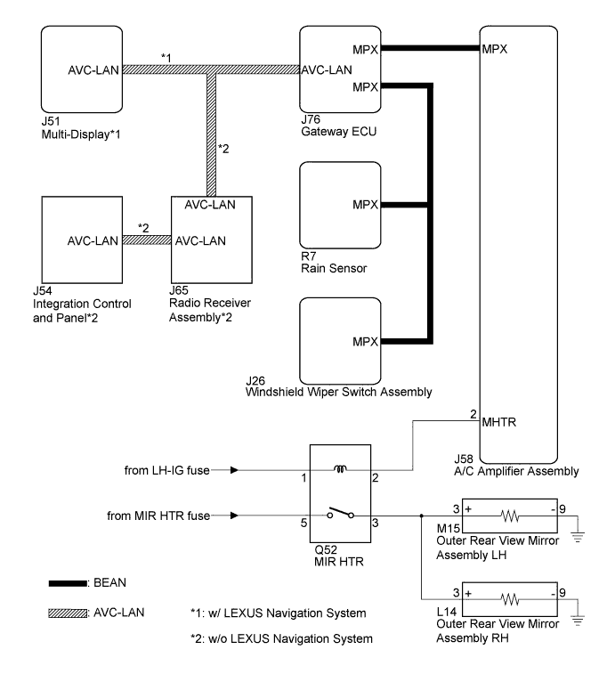
When the window defogger switch, which is built into the multi-display assembly*1 or integration control and panel*2, is operated, the operation signals are transmitted to the A/C amplifier assembly through AVC-LAN and BEAN. When the A/C amplifier assembly receives the signals, it turns on the MIR HTR relay to operate the mirror heater. When the defogger switch is turned off, the mirror heater also turns off simultaneously.
Wiper linked function:
-
When the rain sensor detects raindrops while the windshield wiper switch assembly is in the AUTO position, the rain sensor sends a wiper operation request signal to the A/C amplifier assembly. When the A/C amplifier assembly receives the wiper operation request signal, it controls the MIR HTR relay to operate the mirror heater. After the request signal from the rain sensor stops and 15 minutes elapses, the A/C amplifier assembly turns off the MIR HTR relay to turn off the mirror heater.
-
When the windshield wiper switch assembly is moved to the INT, LO, HI or MIST position, the windshield wiper switch assembly sends a switch position signal to the A/C amplifier. When the A/C amplifier receives this signal, it controls the MIR HTR relay to operate the mirror heater. After the switch position signal from the windshield wiper switch assembly stops and 15 minutes elapses, the A/C amplifier assembly turns off the MIR HTR relay to turn off the mirror heater.
Note
-
The power mirror control system is a part of the multiplex communication system. This system features shared communication wiring that reduces the wiring complexity of the communication lines. The first step in any repair is to confirm the proper operation of the communication system. Proceed with troubleshooting after the communication has been verified (See Multiplex Communication System, Click here.
-
The mirror heater operation is linked with the defogger system or wiper and washer system. Confirm that these systems are operating normally before starting the inspection.
-
*1: w/ LEXUS Navigation system
-
*2: w/o LEXUS Navigation system
WIRING DIAGRAM
INSPECTION PROCEDURE
Note
-
The power mirror control system is a part of the multiplex communication system. This system features shared communication wiring that reduces the wiring complexity of the communication lines. The first step in any repair is to confirm the proper operation of the communication system. Proceed with troubleshooting after the communication has been verified (See Multiplex Communication System, Click here.
-
The mirror heater operation is linked with the defogger system or wiper and washer system. Confirm that these systems are operating normally before starting the inspection.
PROCEDURE
-
CHECK MULTIPLEX COMMUNICATION SYSTEM
-
Use the intelligent tester to check if the multiplex communication system is functioning normally Click here.
NG 
GO TO MULTIPLEX COMMUNICATION SYSTEM Click here
OK 
-
-
PERFORM ACTIVE TEST USING INTELLIGENT TESTER
-
Connect the intelligent tester to the DLC3.
-
Turn the engine switch on (IG).
-
Enter the following menus: Body / Air Conditioner / Active Test.
-
Perform an Active Test according to the display on the tester.
Tester Display Test Part Control Range Diagnostic Note Mirror Heater Mirror heater operation OFF / ON - OK Mirrors become warm.
NG 
PERFORM ACTIVE TEST USING INTELLIGENT TESTER Click here
OK
-
-
REPLACE AIR CONDITIONING AMPLIFIER ASSEMBLY
-
Replace the air conditioning amplifier assembly Click here
NEXT
-
-
CONFIRM MIRROR HEATER OPERATION
-
Turn the engine switch on (IG).
-
Check mirror heater operation.
Result Result Proceed to Mirrors become warm A Mirrors do not operate linked with automatic wiper B Mirrors do not operate linked with windshield wiper switch assembly C
B
REPLACE RAIN SENSOR Click here
C
REPAIR WINDSHIELD WIPER SWITCH ASSEMBLY Click here
A 
END (AIR CONDITIONING AMPLIFIER ASSEMBLY WAS DEFECTIVE)
-
-
PERFORM ACTIVE TEST USING INTELLIGENT TESTER
-
Select the Active Test, use the intelligent tester to issue a control command, and then check heater mirror relay operation.
-
Check that operation sound of the heater mirror relay can be heard.
OK Operation sound of the heater mirror relay can be heard.
NG
INSPECT HEATER MIRROR RELAY Click here
OK
-
-
INSPECT HEATER MIRROR RELAY
-
Remove the heater mirror relay.
-
Measure the resistance according to the value(s) in the table below.
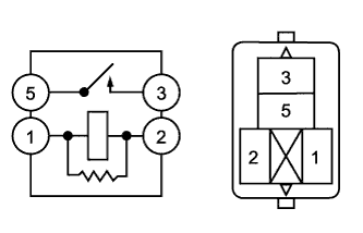
Standard Resistance Tester Connection Condition Specified Condition 3 - 5 When battery voltage is applied to terminals 1 and 2 Below 1 Ω 3 - 5 When battery voltage is not applied to terminals 1 and 2 10 kΩ or higher
NG
REPLACE HEATER MIRROR RELAY
OK
-
-
CHECK HARNESS AND CONNECTOR (HEATER MIRROR RELAY - BATTERY)
-
Measure the voltage according to the table below.
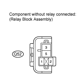
Standard Voltage Tester Connection Condition Specified Condition Q52-5 - Body ground Always 11 to 14 V
NG
REPAIR OR REPLACE HARNESS OR CONNECTOR (HEATER MIRROR RELAY - BATTERY)
OK
-
-
CHECK HARNESS AND CONNECTOR (HEATER MIRROR RELAY - OUTER REAR VIEW MIRROR ASSEMBLY)
-
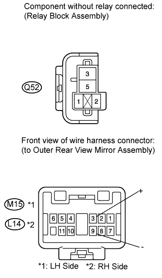
Disconnect the L14 and M15 connectors.
-
Measure the resistance according to the value(s) in the table below.
Standard Resistance Outer Rear View Mirror Assembly LH Tester Connection Condition Specified Condition Q52-3 - M15-3 (+) Always Below 1 Ω Q52-3 - Body ground Always 10 kΩ or higher M15-9 (-) - Body ground Always Below 1 Ω Outer Rear View Mirror Assembly RH Tester Connection Condition Specified Condition Q52-3 - L14-3 (+) Always Below 1 Ω Q52-3 - Body ground Always 10 kΩ or higher L14-9 (-) - Body ground Always Below 1 Ω
NG
REPAIR OR REPLACE HARNESS OR CONNECTOR (HEATER MIRROR RELAY - OUTER REAR VIEW MIRROR ASSEMBLY)
OK
REPLACE OUTER REAR VIEW MIRROR ASSEMBLY Click here
-
-
INSPECT HEATER MIRROR RELAY
-
Remove the heater mirror relay.
-
Measure the resistance according to the value(s) in the table below.
Standard Resistance Tester Connection Condition Specified Condition 3 - 5 When battery voltage is applied to terminals 1 and 2 Below 1 Ω 3 - 5 When battery voltage is not applied to terminals 1 and 2 10 kΩ or higher
NG
REPLACE HEATER MIRROR RELAY
OK
-
-
CHECK HARNESS AND CONNECTOR (HEATER MIRROR RELAY - BATTERY)
-
Measure the voltage according to the value(s) in the table below.
Standard Voltage Tester Connection Condition Specified Condition Q52-1 - Body ground Engine switch on (IG) 11 to 14 V
NG
REPAIR OR REPLACE HARNESS OR CONNECTOR (HEATER MIRROR RELAY - BATTERY)
OK
-
-
CHECK HARNESS AND CONNECTOR (HEATER MIRROR RELAY - A/C AMPLIFIER ASSEMBLY)
-
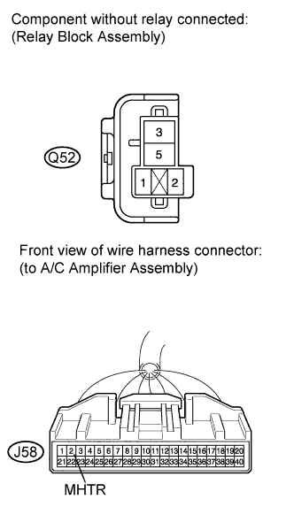
Disconnect the J58 connector.
-
Measure the resistance according to the value(s) in the table below.
Standard Resistance Tester Connection Condition Specified Condition Q52-2 - J58-2 (MHTR) Always Below 1 Ω Q52-2 - Body ground Always 10 kΩ or higher
NG
REPAIR OR REPLACE HARNESS OR CONNECTOR (HEATER MIRROR RELAY - A/C AMPLIFIER ASSEMBLY)
OK
REPLACE AIR CONDITIONING AMPLIFIER ASSEMBLY Click here
-