POWER MIRROR CONTROL SYSTEM Power Source Circuit
DESCRIPTION
This is the power source circuit for the outer mirror control ECU.
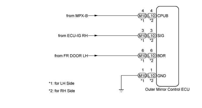
WIRING DIAGRAM
INSPECTION PROCEDURE
PROCEDURE
-
CHECK HARNESS AND CONNECTOR (OUTER MIRROR CONTROL ECU POWER SOURCE)
-
Disconnect the M10 connector*1.
-
Disconnect the L10 connector*2.
-
Measure the voltage according to the value(s) in the table below.
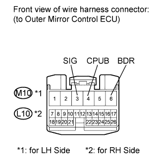
Outer mirror control ECU RH Standard Voltage Tester Connection Condition Specified Condition M10-6 (BDR) - Body ground*1
L10-6 (BDR) - Body ground*2
Always 11 to 14 V M10-4 (CPUB) - Body ground*1
L10-4 (CPUB) - Body ground*2
Always 11 to 14 V M10-3 (SIG) - Body ground*1
L10-3 (SIG) - Body ground*2
Engine switch on (IG) 11 to 14 V Tech Tips
-
*1: for LH side
-
*2: for RH side
-
NG 
REPAIR OR REPLACE HARNESS OR CONNECTOR
OK 
-
-
CHECK HARNESS AND CONNECTOR
-
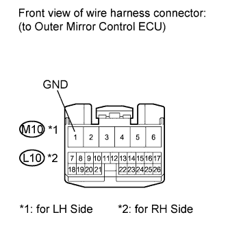
Measure the resistance according to the value(s) in the table below.
Standard Resistance Tester Connection Condition Specified Condition M10-1 (GND) - Body ground
L10-1 (GND) - Body ground
Always Below 1 Ω
NG
REPAIR OR REPLACE HARNESS OR CONNECTOR
OK 
PROCEED TO NEXT CIRCUIT INSPECTION SHOWN IN PROBLEM SYMPTOMS TABLE
-