POWER MIRROR CONTROL SYSTEM Reverse Shift-linked Function of Power Mirrors does not Operate
DESCRIPTION
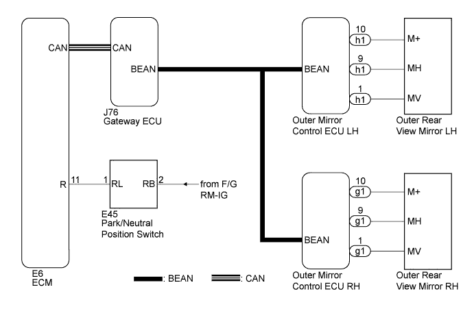
After the ECM receives a reverse signal from the park/neutral position switch, the ECM sends a reverse signal to the outer mirror control ECU via the CAN and BEAN communication systems. The outer mirror control ECU activates the mirror motor in response to the reverse signal.
Note
-
The reverse shift linked function of the power mirrors will not operate when the mirror select switch is in the neutral position (between "L" and "R").
-
The power mirror control system is a part of the multiplex communication system. This system features shared communication wiring that reduces the wiring complexity of the communication lines. The first step in any repair is to confirm the proper operation of the communication system. Proceed with troubleshooting after the communication has been verified (See the Multiplex Communication System: Click here.
WIRING DIAGRAM
INSPECTION PROCEDURE
CAUTION:
The following diagnosis procedure is based on the premise that the seat memory system is functioning. If the seat memory system is not functioning, Click here.
The following diagnosis procedure is based on the premise that the power mirrors can be adjusted with the power mirror switch. If the power mirrors cannot be adjusted, Click here.
Tech Tips
HINT: Terminals MV, M+ and MH are the terminals for the motors in the mirror. Terminals VSSR, VC, HSSR and E1 are for the position sensors. The H in MH and HSSR indicates horizontal. The V in MV and VSSR indicates vertical.
PROCEDURE
-
CHECK CAN COMMUNICATION SYSTEM
-
Check for CAN communication system DTCs Click here.
Tech Tips
If CAN communication system DTCs are output, inspect those DTCs first.
OK DTC is not output.
NG 
GO TO CAN COMMUNICATION SYSTEM Click here
OK 
-
-
CHECK MULTIPLEX COMMUNICATION SYSTEM
-
Check for multiplex communication system DTCs Click here.
Tech Tips
If multiplex communication system DTCs are output, inspect those DTCs first.
OK DTC is not output.
NG
GO TO MULTIPLEX COMMUNICATION SYSTEM Click here
OK
-
-
CHECK FOR DTC (SFI SYSTEM)
-
Check for DTC P0705 (Transmission Range Sensor Circuit Malfunction).
Tech Tips
If the DTC P0705 (Transmission Range Sensor Circuit Malfunction) is output, inspect that DTC first.
OK DTC is not output.
NG
GO TO SFI SYSTEM (DTC P0705) Click here
OK
-
-
CHECK OPERATION (MEMORY SWITCH OPERATION)
-
Check mirror operation Click here.
-
Check if the recall function operates normally.
OK Mirror position recall function is normal.
NG
GO TO OTHER FLOW CHART (Power Mirror do not Return to Memorized Position) Click here
OK
-
-
CONFIRM REVERSE SHIFT-LINKED FUNCTION
-
Turn the engine switch on (IG).
-
Make sure that the brake pedal is depressed, and set the parking brake.
-
Move the shift lever from P to R.
-
Check reverse shift-linked function.
Result Result Proceed to Only one mirror moves normally due to reverse shift-linked function A Neither mirror moves normally due to reverse shift-linked function B
B 
REPLACE GATEWAY ECU Click here
A 
REPLACE OUTER MIRROR CONTROL ECU (SIDE THAT DOES NOT OPERATE NORMALLY) Click here
-
-
REPLACE GATEWAY ECU
-
Replace the gateway ECU with a normally functioning ECU or new one.
NEXT
-
-
CONFIRM REVERSE SHIFT-LINKED FUNCTION
-
Turn the engine switch on (IG).
-
Make sure that the brake pedal is depressed.
-
Move the shift lever from P to R.
-
Check reverse shift-linked function.
OK Reverse shift-linked function is normal.
NG
REPLACE ECM Click here
OK
END
-