POWER MIRROR CONTROL SYSTEM Power Mirrors do not Return to Memorized Position
DESCRIPTION
The power mirrors are linked with the seat memory system for the driver seat. When M1, M2 or M3 on the driver seat memory switch is pressed, the outer mirror control ECU LH and RH drive the mirror motors. The horizontal and vertical position sensors in the mirrors are used for position feedback.
Note
The power mirror control system is a part of the multiplex communication system. This system features shared communication wiring that reduces the wiring complexity of the communication lines. The first step in any repair is to confirm the proper operation of the communication system. Proceed with troubleshooting after the communication has been verified (See Multiplex Communication System: Click here.
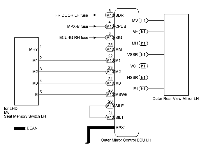
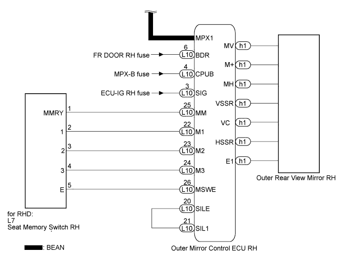
WIRING DIAGRAM
INSPECTION PROCEDURE
Note
The following diagnosis procedure is based on the premise that the seat memory system is functioning and that memory positions have been set. If the seat memory system is not functioning, Click here.
The following diagnosis procedure is based on the premise that the power mirrors can be adjusted with the power mirror switch. If the power mirrors cannot be adjusted, Click here.
Tech Tips
Terminals MV, M+ and MH are the terminals for the motors in the mirror. Terminals VSSR, VC, HSSR and E1 are for the position sensors. The H in MH and HSSR indicates horizontal. The V in MV and VSSR indicates vertical.
PROCEDURE
-
CHECK MIRROR MEMORY RECALL FUNCTION
-
Check mirror memory recall function.
-
Move the shift lever to P.
-
Turn the engine switch on (IG).
-
Push the driver side seat memory switch.
Result Result Proceed to Only one mirror moves due to memory recall function A Both Mirrors move due to memory recall function B
-
B 
READ VALUE USING INTELLIGENT TESTER (DRIVER SIDE SEAT MEMORY SWITCH OPERATION) Click here
A 
-
-
READ VALUE USING INTELLIGENT TESTER (MIRROR POSITION SENSOR)
-
Connect the intelligent tester to the DLC3.
-
Turn the engine switch on (IG).
-
Enter the following menus: Body / Mirror L or Mirror R / Data List.
Tech Tips
-
Select the ECU for the side with the malfunctioning mirror.
-
Mirror L is Outer Mirror Control ECU LH, and Mirror R is Outer Mirror Control ECU RH.
-
-
According to the display on the intelligent tester, read the Data List.
Mirror L or Mirror R Tester Display Measurement Item / Range Normal Condition Diagnostic Note Mir Position Sensor (V) Vertical mirror position MIN: 0, MAX: 5 V Within range from 0 to 5 V Depends on mirror position Mir Position Sensor (H) Horizontal mirror position / MIN: 0, MAX: 5 V Within range from 0 to 5 V Depends on mirror position OK The Data List values change in accordance with mirror movement.
NG 
REPLACE OUTER REAR VIEW MIRROR Click here
OK
-
-
READ VALUE USING INTELLIGENT TESTER (MIRROR MEMORY)
-
Connect the intelligent tester to the DLC3.
-
Turn the engine switch on (IG).
-
Enter the following menus: Body / Mirror Lor Mirror R / Data List.
Tech Tips
-
Select the ECU for the side with the malfunctioning mirror.
-
Mirror L is Outer Mirror Control ECU LH, and Mirror R is Outer Mirror Control ECU RH.
-
-
According to the display on the intelligent tester, read the Data List.
Mirror L or Mirror R Tester Display Measurement Item/Range Normal Condition Diagnostic Note Mirror Memory No.1 Mirror position memorized in memory switch M1 / Not Mem or Mem Mem: Memorized
Not Mem: Not memorized
- Mirror Memory No.2 Mirror position memorized in memory switch M2 / Not Mem or Mem Mem: Memorized
Not Mem: Not memorized
- Mirror Memory No.3 Mirror position memorized in memory switch M3 / Not Mem or Mem Mem: Memorized
Not Mem: Not memorized
-
-
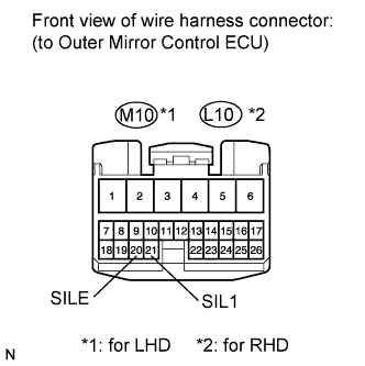
*1: for LHD
-
*2: for RHD
OK "Mem" appears on the intelligent tester display. -
NG
CHECK HARNESS AND CONNECTOR (OUTER MIRROR CONTROL ECU - BATTERY AND BODY GROUND) Click here
OK 
REPLACE OUTER MIRROR CONTROL ECU Click here
-
-
CHECK HARNESS AND CONNECTOR (OUTER MIRROR CONTROL ECU - BATTERY AND BODY GROUND)
-
for LH side
-
Disconnect the M10 connector.
-
Measure the voltage according to the value(s) in the table below.
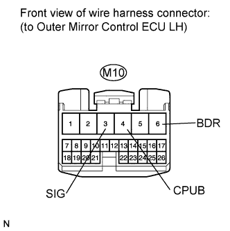
Standard Voltage Tester Connection Condition Specified Condition M10-6 (BDR) - Body ground Always 11 to 14 V M10-4 (CPUB) - Body ground Always 11 to 14 V M10-3 (SIG) - Body ground Engine switch on (IG) 11 to 14 V
-
-
for RH side
-
Disconnect the L10 connector.

-
Measure the voltage according to the value(s) in the table below.
Standard Voltage Tester Connection Condition Specified Condition L10-6 (BDR) - Body ground Always 11 to 14V L10-4 (CPUB) - Body ground Always 11 to 14 V L10-3 (SIG) - Body ground Engine switch on (IG) 11 to 14 V
-
NG
REPAIR OR REPLACE HARNESS OR CONNECTOR (OUTER MIRROR CONTROL ECU - BATTERY AND BODY GROUND)
OK
REPLACE OUTER MIRROR CONTROL ECU Click here
-
-
READ VALUE USING INTELLIGENT TESTER (DRIVER SIDE SEAT MEMORY SWITCH OPERATION)
-
Connect the intelligent tester to the DLC3.
-
Turn the engine switch on (IG).
-
Enter the following menus: Body / Driver Seat/ Data List.
-
According to the display on the intelligent tester, read the Data List.
Driver Seat Tester Display Measurement Item/Range Normal Condition Diagnostic Note M3 Switch Seat memory switch M3 signal/ON or OFF ON: Seat memory switch M3 is ON
OFF: Seat memory switch M3 is OFF
- M2 Switch Seat memory switch M2 signal/ON or OFF ON: Seat memory switch M2 is ON
OFF: Seat memory switch M2 is OFF
- M1 Switch Seat memory switch M1 signal/ON or OFF ON: Seat memory switch M1 is ON
OFF: Seat memory switch M1 is OFF
- SET Switch Seat memory switch SET signal/ON or OFF ON: Seat memory set switch is ON
OFF: Seat memory set switch is OFF
- OK "ON" (each switch is on) and "OFF" (each switch is off) appear on intelligent tester screen.
NG
INSPECT SEAT MEMORY SWITCH Click here
OK
REPLACE FRONT POWER SEAT SWITCH (POSITION CONTROL ECU) Click here
-
-
INSPECT SEAT MEMORY SWITCH
-
for LHD
-
Remove the seat memory switch Click here.
-
Measure the resistance according to the value(s) in the table below.
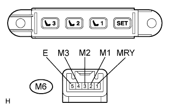
Standard Resistance Tester Connection Condition Specified Condition 1 (MRY) - 5 (E) SET switch is pressed Below 1 Ω 2 (M1) - 5 (E) M1 switch is pressed Below 1 Ω 3 (M2) - 5 (E) M2 switch is pressed Below 1 Ω 4 (M3) - 5 (E) M3 switch is pressed Below 1 Ω 1 (MRY) - 5 (E) SET switch is not pressed 10 kΩ or higher 2 (M1) - 5 (E) M1 switch is not pressed 10 kΩ or higher 3 (M2) - 5 (E) M2 switch is not pressed 10 kΩ or higher 4 (M3) - 5 (E) M3 switch is not pressed 10 kΩ or higher
-
-
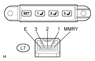
for RHD
-
Remove the seat memory switch Click here.
-
Measure the resistance according to the value(s) in the table below.
Standard Resistance Tester Connection Condition Specified Condition 1 (MMRY) - 5 (E) SET switch is pressed Below 1 Ω 2 (1) - 5 (E) M1 switch is pressed Below 1 Ω 3 (2) - 5 (E) M2 switch is pressed Below 1 Ω 4 (3) - 5 (E) M3 switch is pressed Below 1 Ω 1 (MMRY) - 5 (E) SET switch is not pressed 10 kΩ or higher 2 (1) - 5 (E) M1 switch is not pressed 10 kΩ or higher 3 (2) - 5 (E) M2 switch is not pressed 10 kΩ or higher 4 (3) - 5 (E) SET switch is not pressed 10 kΩ or higher
-
NG
REPLACE SEAT MEMORY SWITCH Click here
OK
-
-
CHECK HARNESS AND CONNECTOR (SEAT MEMORY SWITCH - OUTER MIRROR CONTROL ECU)
-
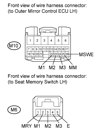
for LHD
-
Disconnect the M10 connector.
-
Measure the resistance according to the value(s) in the table below.
Standard Resistance Tester Connection Condition Specified Condition M10-22 (M1) - M6-2 (M1) Always Below 1 Ω M10-23 (M2) - M6-3 (M2) Always Below 1 Ω M10-24 (M3) - M6-4 (M3) Always Below 1 Ω M10-25 (MM) - M6-1 (MRY) Always Below 1 Ω M10-26 (MSWE) - M6-5 (E) Always Below 1 Ω M10-22 (M1) - Body ground Always 10 kΩ or higher M10-23 (M2) - Body ground Always 10 kΩ or higher M10-24 (M3) - Body ground Always 10 kΩ or higher M10-25 (MM) - Body ground Always 10 kΩ or higher M10-26 (MSWE) - Body ground Always 10 kΩ or higher
-
-
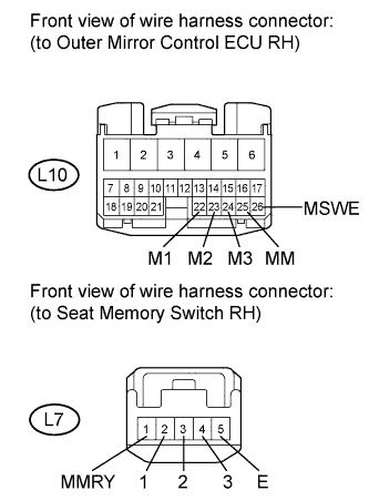
for RHD
-
Disconnect the L10 connector.
-
Measure the resistance according to the value(s) in the table below.
Standard Resistance Tester Connection Condition Specified Condition L10-22 (M1) - L7-2 (1) Always Below 1 Ω L10-23 (M2) - L7-3 (2) Always Below 1 Ω L10-24 (M3) - L7-4 (3) Always Below 1 Ω L10-25 (MM) - L7-1 (MMRY) Always Below 1 Ω L10-26 (MSWE) - L7-5 (E) Always Below 1 Ω L10-22 (M1) - Body ground Always 10 kΩ or higher L10-23 (M2) - Body ground Always 10 kΩ or higher L10-24 (M3) - Body ground Always 10 kΩ or higher L10-25 (MM) - Body ground Always 10 kΩ or higher L10-26 (MSWE) - Body ground Always 10 kΩ or higher
-
NG
REPAIR OR REPLACE HARNESS OR CONNECTOR (SEAT MEMORY SWITCH - OUTER MIRROR CONTROL ECU)
OK
-
-
CHECK HARNESS AND CONNECTOR (OUTER MIRROR CONTROL ECU - OUTER MIRROR CONTROL ECU)
-
Measure the resistance according to the value(s) in the table below.
Tech Tips
-
For LHD, check at the outer mirror control ECU LH connector.
-
For RHD, check at the outer mirror control ECU RH connector.
for LHD Standard Resistance Tester Connection Condition Specified Condition M10-20 (SILE) - M10-21 (SIL1) Always Below 1 Ω M10-20 (SILE) - Body ground Always 10 kΩ or higher for RHD Standard Resistance Tester Connection Condition Specified Condition L10-20 (SILE) - L10-21 (SIL1) Always Below 1 Ω L10-20 (SILE) - Body ground Always 10 kΩ or higher -
NG
REPAIR OR REPLACE HARNESS OR CONNECTOR (OUTER MIRROR CONTROL ECU - OUTER MIRROR CONTROL ECU)
OK
-
-
REPLACE OUTER MIRROR CONTROL ECU (DRIVER SIDE)
-
Replace outer mirror control ECU Click here.
NEXT
-
-
CHECK MIRROR MEMORY RECALL FUNCTION
-
Check mirror memory recall function.
-
Move the shift lever to P.
-
Turn the engine switch on (IG).
-
Push the driver side seat memory switch.
OK Mirror memory recall function is normal.
-
NG
REPLACE FRONT POWER SEAT SWITCH (POSITION CONTROL ECU) Click here
OK
END
-