LUGGAGE COMPARTMENT DOOR OPENER SYSTEM TERMINALS OF ECU

-
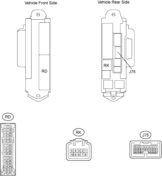
CHECK MAIN BODY ECU RH (COWL SIDE JUNCTION BLOCK RH)
-
Disconnect the RD and RK junction block connectors.
-
Disconnect the J75 ECU connector.
-
Measure the resistance and voltage according to the value(s) in the table below.
Tester Connection Wiring Color Terminal Description Condition Specified Condition RK-5 (BECU) - Body ground G-R - Body ground Battery (power supply) Always 11 to 14 V RD-17 (GND1) - Body ground W-B - Body ground Ground Always Below 1 Ω RD-7 (GND2) - Body ground W-B - Body ground Ground Always Below 1 Ω If the result is not as specified, there may be a malfunction on the wire harness side.
-
Reconnect the RD and RK junction block connectors.
-
Reconnect the J75 ECU connector.
-
Measure the voltage according to the value(s) in the table below.
Tester Connection Wiring Color Terminal Description Condition Specified Condition J75-2 (TSW) - Body ground LG - Body ground Luggage compartment door opener main switch signal input Luggage compartment door opener main switch OFF 11 to 14 V J75-2 (TSW) - Body ground LG - Body ground Luggage compartment door opener main switch signal input Luggage compartment door opener main switch ON Below 1 V J75-3 (TKUL) - Body ground P - Body ground Luggage compartment door opener inner switch signal input Luggage compartment door opener inner switch OFF 11 to 14 V J75-3 (TKUL) - Body ground P - Body ground Luggage compartment door opener inner switch signal input Luggage compartment door opener inner switch ON Below 1 V If the result is not as specified, the ECU may have a malfunction.
-