WINDOW DEFOGGER SYSTEM Rear Window Defogger System does not Operate
DESCRIPTION
-
w/ Navigation System
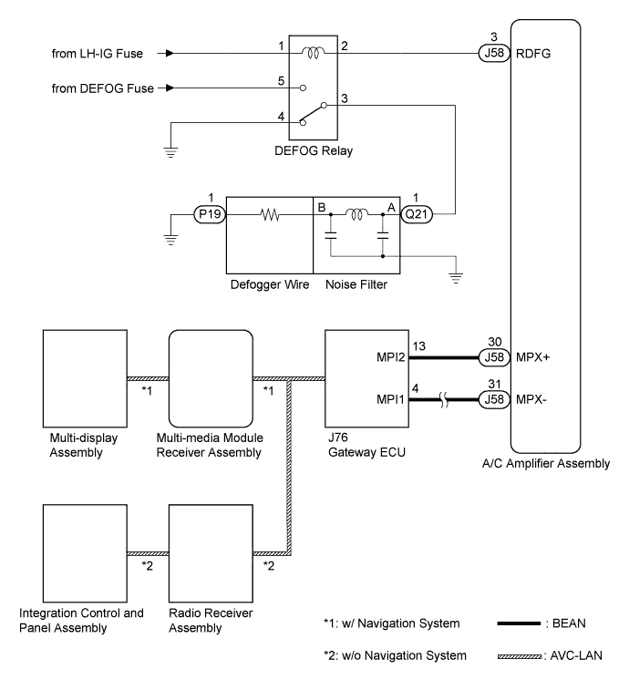
When the rear window defogger switch, which is built into the multi-display assembly, is operated, the operation signals are transmitted to the A/C amplifier assembly through AVC-LAN and BEAN. When the A/C amplifier assembly receives the signals, it turns on the DEFOG relay to operate the rear window defogger.
-
w/o Navigation System
When the rear window defogger switch, which is built into the integration control and panel assembly, is operated, the operation signals are transmitted to the A/C amplifier assembly through AVC-LAN and BEAN. When the A/C amplifier assembly receives the signals, it turns on the DEFOG relay to operate the rear window defogger.
WIRING DIAGRAM
INSPECTION PROCEDURE
PROCEDURE
-
PERFORM ACTIVE TEST USING INTELLIGENT TESTER
-
Connect the intelligent tester to the DLC3.
-
Turn the engine switch on (IG).
-
Turn the tester on.
-
Enter the following menus: Body Electrical / Air Conditioner / Active Test.
-
Check the value(s) by referring to the table below, and then check the window defogger operation Click here.
Air Conditioner Tester Display Test Part Control Range Diagnostic Note Defogger Rly-R Turns rear window defogger OFF/ON - OK Rear window defogger normally operates.
NG 
CHECK HARNESS AND CONNECTOR (DEFOG RELAY - BATTERY) Click here
OK 
-
-
CHECK DTC (MULTIPLEX COMMUNICATION SYSTEM)
-
Use the intelligent tester to check if the multiplex communication system is functioning normally Click here.
Result Result Proceed to Multiplex communication DTC is not output (w/o navigation system). A Multiplex communication DTC is output. B Multiplex communication DTC is not output (w/ navigation system). C
B 
GO TO MULTIPLEX COMMUNICATION Click here
C
CHECK FOR DTC (NAVIGATION SYSTEM) Click here
A
-
-
CHECK DTC (AUDIO VISUAL SYSTEM)
-
Use the intelligent tester to check if the audio and visual system is functioning normally Click here.
Result Result Proceed to Audio and visual system DTC is output. A Audio and visual system DTC is not output. B
B
GO TO AUDIO AND VISUAL SYSTEM Click here
A
-
-
REPLACE INTEGRATION CONTROL AND PANEL ASSEMBLY
-
Replace the integration control and panel assembly Click here.
NEXT
-
-
CONFIRM REAR WINDOW DEFOGGER OPERATES
-
Turn the engine switch on (IG), press the window defogger switch, and check that window defogger operates Click here.
OK Rear window defogger normally operates.
NG
REPLACE RADIO RECEIVER ASSEMBLY Click here
OK 
END
-
-
REPLACE RADIO RECEIVER ASSEMBLY
-
Replace the radio receiver assembly Click here.
NEXT
-
-
CONFIRM REAR WINDOW DEFOGGER OPERATES
-
Turn the engine switch on (IG), press the window defogger switch, and check that window defogger operates Click here.
OK Rear window defogger normally operates.
NG
REPLACE GATEWAY ECU Click here
OK
END
-
-
REPLACE GATEWAY ECU
-
Replace the gateway ECU Click here.
NEXT
-
-
CONFIRM REAR WINDOW DEFOGGER OPERATES
-
Turn the engine switch on (IG), press the window defogger switch, and check that window defogger operates Click here.
OK Rear window defogger normally operates.
NG
REPLACE A/C AMPLIFIER ASSEMBLY Click here
OK
END
-
-
CHECK FOR DTC (NAVIGATION SYSTEM)
-
Use the intelligent tester to check if the navigation system is functioning normally Click here.
Result Result Proceed to Navigation system DTC is not output. A Navigation system DTC is output. B
B
GO TO NAVIGATION SYSTEM Click here
A
-
-
REPLACE MULTI-DISPLAY ASSEMBLY
-
Replace the multi-display assembly Click here.
NEXT
-
-
CONFIRM REAR WINDOW DEFOGGER OPERATES
-
Turn the engine switch on (IG), press the window defogger switch, and check that window defogger operates Click here.
OK Rear window defogger normally operates.
NG
REPLACE GATEWAY ECU Click here
OK
END
-
-
REPLACE MULTI-MEDIA MODULE RECEIVER ASSEMBLY
-
Replace the multi-media module receiver assembly Click here.
NEXT
-
-
CONFIRM REAR WINDOW DEFOGGER OPERATES
-
Turn the engine switch on (IG), press the window defogger switch, and check that window defogger operates Click here.
OK Rear window defogger normally operates.
NG
REPLACE GATEWAY ECU Click here
OK
END
-
-
REPLACE GATEWAY ECU
-
Replace the gateway ECU Click here.
NEXT
-
-
CONFIRM REAR WINDOW DEFOGGER OPERATES
-
Turn the engine switch on (IG), press the window defogger switch, and check that window defogger operates Click here.
OK Rear window defogger normally operates.
NG
REPLACE A/C AMPLIFIER ASSEMBLY Click here
OK
END
-
-
CHECK HARNESS AND CONNECTOR (DEFOG RELAY - BATTERY)
-

Disconnect the DEFOG relay from engine room No. 1 relay block and junction block.
-
Measure the voltage according to the value(s) in the table below.
Standard Voltage Tester Connection Condition Specified Condition Engine room No. 1 relay block and junction block DEFOG relay terminal 1 - Body ground Engine switch on (IG) 11 to 14 V
NG
REPAIR OR REPLACE HARNESS OR CONNECTOR, OR LH-IG FUSE
OK
-
-
CHECK HARNESS AND CONNECTOR (DEFOG RELAY- BATTERY)
-

Measure the voltage according to the value(s) in the table below.
Standard Voltage Tester Connection Condition Specified Condition Engine room No. 1 relay block and junction block DEFOG relay terminal 5 - Body ground Always 11 to 14 V
NG
REPAIR OR REPLACE HARNESS OR CONNECTOR, OR DEFOG FUSE
OK
-
-
INSPECT DEFOG RELAY
-

Measure the resistance of the DEFOG relay.
Standard Resistance Tester Condition Condition Specified Condition 3 - 4 When battery voltage is not applied between terminals. Below 1 Ω 3 - 5 When battery voltage is not applied between terminals. 10 kΩ or higher 3 - 5 When battery voltage is applied to terminals 1 and 2. Below 1 Ω
NG
REPLACE DEFOG RELAY
OK
-
-
CHECK HARNESS AND CONNECTOR (A/C AMPLIFIER - DEFOG RELAY)
-

Reconnect the DEFOG relay.
-
Disconnect J58 A/C amplifier assembly connector.
-
Measure the voltage according to the value(s) in the table below.
Standard Voltage Tester Connection Condition Specified Condition J58-3 (RDFG) - Body ground Engine switch on (IG) 11 to 14 V
NG
REPAIR OR REPLACE HARNESS OR CONNECTOR
OK
-
-
INSPECT A/C AMPLIFIER ASSEMBLY
-

Reconnect the J58 A/C amplifier connector.
-
Measure the voltage according to the value(s) in the table below.
Standard Voltage Tester Connection Switch Condition Specified Condition J58-3 (RDFG) - Body ground Push the window defogger switch on Below 1 V
NG
REPLACE A/C AMPLIFIER ASSEMBLY Click here
OK
-
-
CHECK HARNESS AND CONNECTOR (DEFOG RELAY - REAR DEFOGGER WIRE)
-
Disconnect the DEFOG relay and defogger wire connectors.
-
Measure the resistance according to the value(s) in the table below.
Standard Resistance Tester Connection Condition Specified Condition Engine room No. 1 relay block and junction block DEFOG relay terminal 3 - Q21-1 Always Below 1 Ω
NG
REPAIR OR REPLACE HARNESS OR CONNECTOR
OK
-
-
INSPECT NOISE FILTER
-

Disconnect the noise filter connectors.
-
Measure the resistance according to the value(s) in the table below.
Standard Resistance Tester Connection Condition Specified Condition A-1 - B-1 Always Below 1 Ω
NG
REPLACE NOISE FILTER
OK
-
-
CHECK HARNESS AND CONNECTOR (REAR DEFOGGER WIRE - BODY GROUND)
-
Disconnect the rear defogger wire connector.
-
Measure the resistance according to the value(s) in the table below.
Standard Resistance Tester Connection Condition Specified Condition P19-1 - Body ground Always Below 1 Ω
NG
REPAIR OR REPLACE HARNESS OR CONNECTOR
OK
REPAIR REAR WINDOW DEFOGGER WIRE Click here
-