SLIDING ROOF SYSTEM Sliding Roof does not Move by Operating Sliding Roof Control Switch
DESCRIPTION
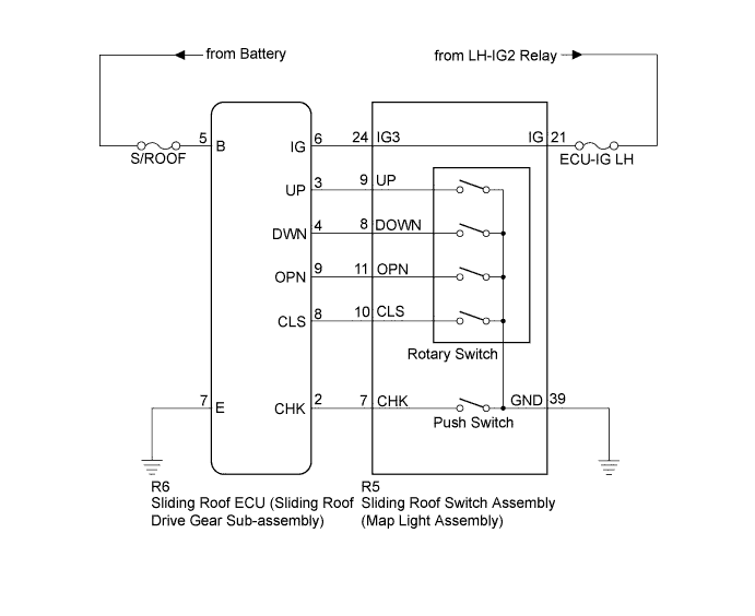
The sliding roof ECU (sliding roof drive gear sub-assembly) receives switch slide and tilt signals and drives its built-in motor.
WIRING DIAGRAM
INSPECTION PROCEDURE
Note
When the sliding roof drive gear sub-assembly is reinstalled or replaced, the sliding roof drive gear sub-assembly must be initialized Click here.
PROCEDURE
-
PERFORM ACTIVE TEST USING INTELLIGENT TESTER (SLIDING ROOF OPERATION)
-
Connect the intelligent tester to the DLC3.
-
Turn the engine switch on (IG).
-
Turn the tester on.
-
Enter the following menus: Body / Sliding Roof / Active Test.
-
Perform the Active Test according to the display on the tester.
Sliding Roof Tester Display Test Part Control Range Diagnostic Note Slide Roof Operate sliding roof CLOS/UP / OFF - Slide Roof Operate sliding roof OPN/DWN / OFF - OK Sliding roof operates normally.
NG 
REPLACE SLIDING ROOF ECU (SLIDING ROOF DRIVE GEAR SUB-ASSEMBLY) Click here
OK 
-
-
READ VALUE USING INTELLIGENT TESTER
-
Connect the intelligent tester to the DLC3.
-
Turn the engine switch on (IG).
-
Turn the tester on.
-
Enter the following menus: Body / Sliding Roof / Data List.
-
Read the Data List according to the display on the tester.
Sliding Roof Tester Display Measurement Item/Range Normal Condition Diagnostic Note Hall IC1 Pulse Sliding roof operation signal/LO or HI LO: Sliding roof motor is not operating
HI: Sliding roof motor is operating
- Hall IC1 Status Sliding roof operation signal/NORMAL or LOCK NORMAL: Sliding roof motor is operating
LOCK: Sliding roof motor is not operating
- Hall IC2 Pulse Sliding roof operation signal/LO or HI LO: Sliding roof motor is not operating
HI: Sliding roof motor is operating
- Hall IC2 Status Sliding roof operation signal/NORMAL or LOCK NORMAL: Sliding roof motor is operating
LOCK: Sliding roof motor is not operating
-
NG
REPLACE SLIDING ROOF ECU (SLIDING ROOF DRIVE GEAR SUB-ASSEMBLY) Click here
OK
-
-
INSPECT FUSE
-
Remove the S/ROOF and ECU-IG LH fuses from cowl side junction block LH.
-
Measure the resistance according to the value(s) in the table below.
Standard Resistance Tester Connection Condition Specified Condition S/ROOF fuse Always Below 1 Ω ECU-IG LH fuse Always Below 1 Ω
NG
REPLACE FUSE
OK
-
-
CHECK HARNESS AND CONNECTOR (SLIDING ROOF ECU - BATTERY, BODY GROUND)
-
Disconnect the R6 ECU connector.
-
Measure the voltage according to the value(s) in the table below.
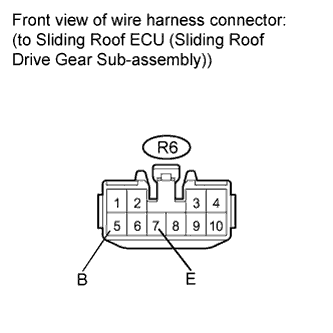
Standard Voltage Tester Connection Condition Specified Condition R6-5 (B) - Body ground Always 11 to 14 V -
Measure the resistance according to the value(s) in the table below.
Standard Resistance Tester Connection Condition Specified Condition R6-7 (E) - Body ground Always Below 1 Ω
NG
REPAIR OR REPLACE HARNESS OR CONNECTOR
OK
-
-
CHECK HARNESS AND CONNECTOR (SLIDING ROOF ECU - LH-IG2 RELAY)
-
Measure the voltage according to the value(s) in the table below.
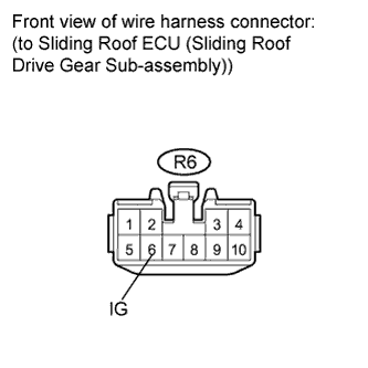
Standard Voltage Tester Connection Switch Condition Specified Condition R6-6 (IG) - Body ground Engine switch on (IG) 11 to 14 V R6-6 (IG) - Body ground Engine switch off Below 1 V
NG 
CHECK HARNESS AND CONNECTOR (SLIDING ROOF SWITCH ASSEMBLY - LH-IG2 RELAY) Click here
OK
-
-
CHECK HARNESS AND CONNECTOR (SLIDING ROOF ECU - SLIDING ROOF SWITCH ASSEMBLY)
-
Disconnect the R5 switch connector.
-
Measure the resistance according to the value(s) in the table below.
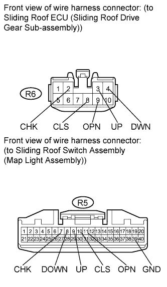
Standard Resistance Tester Connection Condition Specified Condition R6-2 (CHK) - R5-7 (CHK) Always Below 1 Ω R6-8 (CLS) - R5-10 (CLS) Always Below 1 Ω R6-9 (OPN) - R5-11 (OPN) Always Below 1 Ω R6-4 (DWN) - R5-8 (DOWN) Always Below 1 Ω R6-3 (UP) - R5-9 (UP) Always Below 1 Ω R5-39 (GND) - Body ground Always Below 1 Ω R6-2 (CHK) - Body ground Always 10 kΩ or higher R6-8 (CLS) - Body ground Always 10 kΩ or higher R6-9 (OPN) - Body ground Always 10 kΩ or higher R6-4 (DWN) - Body ground Always 10 kΩ or higher R6-3 (UP) - Body ground Always 10 kΩ or higher
NG
REPAIR OR REPLACE HARNESS OR CONNECTOR
OK
-
-
INSPECT SLIDING ROOF SWITCH ASSEMBLY (MAP LIGHT ASSEMBLY)
-
Remove the sliding roof switch assembly (map light assembly) Click here.
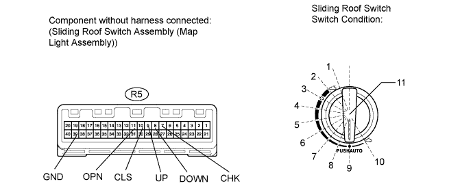
-
Measure the resistance according to the value(s) in the table below.
Standard Resistance Tester Connection Switch Condition Specified Condition R5-8 (DOWN) - R5-39 (GND) 1 Below 100 Ω R5-9 (UP) - R5-39 (GND) 1 1 kΩ or higher R5-10 (CLS) - R5-39 (GND) 1 1 kΩ or higher R5-11 (OPN) - R5-39 (GND) 1 1 kΩ or higher R5-8 (DOWN) - R5-39 (GND) 2 Below 100 Ω R5-9 (UP) - R5-39 (GND) 2 Below 100 Ω R5-10 (CLS) - R5-39 (GND) 2 1 kΩ or higher R5-11 (OPN) - R5-39 (GND) 2 1 kΩ or higher R5-8 (DOWN) - R5-39 (GND) 3 1 kΩ or higher R5-9 (UP) - R5-39 (GND) 3 Below 100 Ω R5-10 (CLS) - R5-39 (GND) 3 1 kΩ or higher R5-11 (OPN) - R5-39 (GND) 3 1 kΩ or higher R5-8 (DOWN) - R5-39 (GND) 4 1 kΩ or higher R5-9 (UP) - R5-39 (GND) 4 Below 100 Ω R5-10 (CLS) - R5-39 (GND) 4 1 kΩ or higher R5-11 (OPN) - R5-39 (GND) 4 Below 100 Ω R5-8 (DOWN) - R5-39 (GND) 5 1 kΩ or higher R5-9 (UP) - R5-39 (GND) 5 1 kΩ or higher R5-10 (CLS) - R5-39 (GND) 5 1 kΩ or higher R5-11 (OPN) - R5-39 (GND) 5 Below 100 Ω R5-8 (DOWN) - R5-39 (GND) 6 1 kΩ or higher R5-9 (UP) - R5-39 (GND) 6 1 kΩ or higher R5-10 (CLS) - R5-39 (GND) 6 Below 100 Ω R5-11 (OPN) - R5-39 (GND) 6 Below 100 Ω R5-8 (DOWN) - R5-39 (GND) 7 1 kΩ or higher R5-9 (UP) - R5-39 (GND) 7 Below 100 Ω R5-10 (CLS) - R5-39 (GND) 7 Below 100 Ω R5-11 (OPN) - R5-39 (GND) 7 Below 100 Ω R5-8 (DOWN) - R5-39 (GND) 8 1 kΩ or higher R5-9 (UP) - R5-39 (GND) 8 Below 100 Ω R5-10 (CLS) - R5-39 (GND) 8 Below 100 Ω R5-11 (OPN) - R5-39 (GND) 8 1 kΩ or higher R5-8 (DOWN) - R5-39 (GND) 9 Below 100 Ω R5-9 (UP) - R5-39 (GND) 9 Below 100 Ω R5-10 (CLS) - R5-39 (GND) 9 Below 100 Ω R5-11 (OPN) - R5-39 (GND) 9 1 kΩ or higher R5-8 (DOWN) - R5-39 (GND) 10 Below 100 Ω R5-9 (UP) - R5-39 (GND) 10 1 kΩ or higher R5-10 (CLS) - R5-39 (GND) 10 Below 100 Ω R5-11 (OPN) - R5-39 (GND) 10 1 kΩ or higher R5-7 (CHK) - R5-39 (GND) 11 Below 100 Ω
NG
REPLACE SLIDING ROOF SWITCH ASSEMBLY (MAP LIGHT ASSEMBLY) Click here
OK 
REPLACE SLIDING ROOF ECU (SLIDING ROOF DRIVE GEAR SUB-ASSEMBLY) Click here
-
-
CHECK HARNESS AND CONNECTOR (SLIDING ROOF SWITCH ASSEMBLY - LH-IG2 RELAY)
-
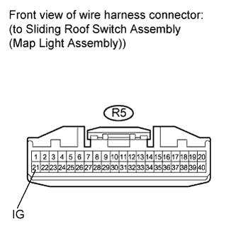
Disconnect the R5 switch connector.
-
Measure the voltage according to the value(s) in the table below.
Standard Voltage Tester Connection Switch Condition Specified Condition R5-21 (IG) - Body ground Engine switch on (IG) 11 to 14 V R5-21 (IG) - Body ground Engine switch off Below 1 V
NG
REPAIR OR REPLACE HARNESS OR CONNECTOR
OK
-
-
CHECK HARNESS AND CONNECTOR (SLIDING ROOF ECU - SLIDING ROOF SWITCH ASSEMBLY)
-
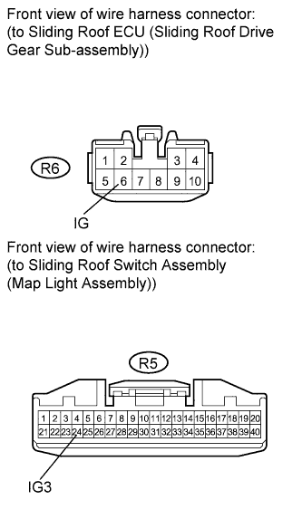
Measure the resistance according to the value(s) in the table below.
Standard Resistance Tester Connection Condition Specified Condition R6-6 (IG) - R5-24 (IG3) Always Below 1 Ω R6-6 (IG) - Body ground Always 10 kΩ or higher
NG
REPAIR OR REPLACE HARNESS OR CONNECTOR
OK
REPLACE SLIDING ROOF SWITCH ASSEMBLY (MAP LIGHT ASSEMBLY) Click here
-