BACK WINDOW GLASS INSTALLATION

-
INSTALL NO. 2 BACK WINDOW GLASS STOPPER (for 2-piece Type)
-
Using a brush or sponge, coat the application area of the No. 2 back window glass stoppers with Primer G.
Note
-
Do not apply too much primer.
-
Allow the primer coating to dry for 3 minutes or more.
-
Do not keep any of the opened Primer G for later use.
Tech Tips
If an area other than specified is coated by accident, wipe off the primer with a clean piece of cloth before it dries.
-
-
Install 2 new No. 2 back window glass stoppers onto the back window glass, as shown in the illustration.
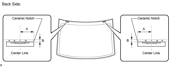
Standard Dimension Area Dimension A 40.0 mm (1.575 in.) B 17.0 mm (0.669 in.) Tech Tips
Only 2-piece type No. 2 back window glass stoppers are supplied. Use the 2-piece type stoppers even if a 1-piece type was used.
-
-
INSTALL NO. 1 BACK WINDOW GLASS STOPPER (for 2-piece Type)
-
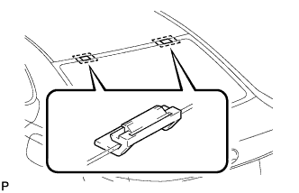
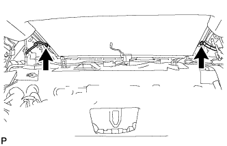
Install 2 new No. 1 back window glass stoppers to the vehicle body as shown in the illustration.
Tech Tips
Only 2-piece type No. 1 back window glass stoppers are supplied. Use the 2-piece type stoppers even if a 1-piece type was used.
-
-
INSTALL BACK WINDOW GLASS DAM
-
Using a brush or sponge, coat the application area of back window glass dam with Primer G.
Note
-
Allow the primer coating to dry for 3 minutes or more.
-
Do not apply too much primer.
-
-
Install a new dam, applying double-sided tape all the way around the glass except where the dam is installed, as shown in the illustration.
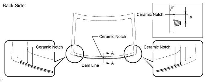
Standard Dimension Area Dimension a 1.5 mm (0.0591 in.) Note
-
Do not apply too much primer.
-
Allow the primer coating to dry for 3 minutes or more.
-
Do not keep any of the opened Primer G for later use.
Tech Tips
If an area other than specified is coated by accident, wipe off the primer with a clean piece of cloth before it dries.
-
-
-
INSTALL NO. 1 BACK WINDOW MOULDING
-
Using a brush or sponge, coat the application area of No. 1 back window moulding with Primer G.
Note
-
Allow the primer to dry for 3 minutes or more.
-
Do not keep any of the opened Primer G for later use.
-
Do not apply too much primer.
Tech Tips
If an area other than specified is coated by accident, wipe off the primer with a clean piece of cloth before it dries.
-
-
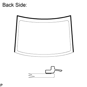
Install a new moulding onto the back window glass as shown in the illustration.
Note
Align the joint of the new moulding with the ceramic notch.
-
-
INSTALL BACK WINDOW GLASS
-
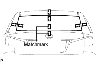
Position the back window glass assembly.
-
Using suction cups place the back window glass assembly in the correct position.
-
Check that the whole contact surface of the back window glass rim is perfectly even.
-
Align the matchmarks on the back window glass and vehicle body.
Note
Check that the back window glass stoppers are attached to the vehicle body correctly.
-
Remove the back window glass assembly.
-
-
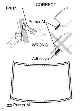
Using a brush, coat the installation surface on the vehicle body with Primer M.
Note
-
Do not coat the adhesive with Primer M.
-
Do not apply too much primer.
-
Allow the primer coating to dry for 3 minutes or more.
-
Do not keep any of the opened Primer M for later use.
Tech Tips
If an area other than specified is coated by accident, wipe off the primer with a clean piece of cloth before it dries.
-
-
Using a brush or sponge, coat the adhesive application area with Primer G.
Note
-
Do not apply too much primer.
-
Allow the primer coating to dry for 3 minutes or more.
-
Do not keep any of the opened Primer G for later use.
Tech Tips
If an area other than specified is coated by accident, wipe off the primer with a clean piece of cloth before it dries.
-
-
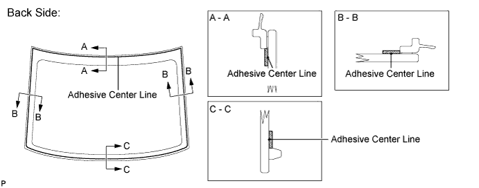
Apply adhesive to the glass.
Adhesive Toyota Genuine Windshield Glass Adhesive or equivalent
-
Cut off the tip of the cartridge nozzle as shown in the illustration.
Tech Tips
After cutting off the tip, use all adhesive within the time described in the table below.
Usage Time Frame Temperature Tack-free Time 35°C (95°F) 15 minutes 20°C (68°F) 1 hour and 40 minutes 5°C (41°F) 8 hours -
Load the sealer gun with the cartridge.
-
Apply adhesive to the back window glass as shown in the illustration.
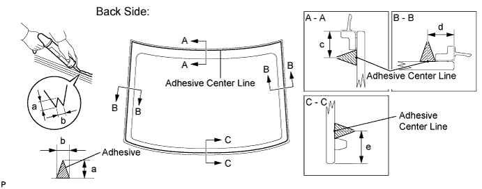
Standard Dimension Area Dimension a 12.0 mm (0.472 in.) b 8.0 mm (0.315 in.) c 9.0 mm (0.354 in.) d 9.0 mm (0.354 in.) e 14.0 mm (0.551 in.)
-
-
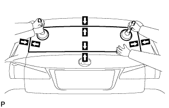
Install the back window glass assembly.
-
Using suction cup position the back window glass so that the matchmarks are aligned, and press it in gently along the rim.
Note
-
Check that the back window glass stoppers are attached to the vehicle body correctly.
-
Check the clearance between the vehicle body and back window glass.
-
-
Lightly press the front surface of the back window glass to ensure a close fit.
Tech Tips
Press the glass with force of 98 N (10 kgf, 22 lbf) or more.
-
Hold the back window glass using protective tape until the applied adhesive becomes hard.
Note
Do not drive the vehicle for the time described in the table below.
Minimum Time Temperature Minimum time prior to driving vehicle 35°C (95°F) 1 hour and 30 minutes 20°C (68°F) 5 hours 5°C (41°F) 24 hours
-
-
Connect the 2 back window defogger connectors.
-
-
INSPECT FOR LEAKS AND REPAIR
-
After the adhesive has hardened, apply water from the outside of the vehicle. Check that no water leaks into the cabin.
-
If water leaks into the cabin, allow the water to dry and add adhesive.
-
Remove the protective tape.
-
-
INSTALL AMPLIFIER ANTENNA ASSEMBLY
-
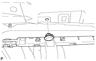
Engage the clip as shown in the illustration to temporarily install the amplifier antenna assembly.
Note
-
Clean the antenna conductors on the rear window with a non-residue solvent where the contact terminals will touch.
-
When installing a new amplifier antenna assembly, do not remove the protective cover until immediately before installation.
-
Do not touch the contact terminals.
-
-
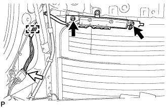
Install the 2 nuts and amplifier antenna assembly.
- Torque:
- 14 N*m { 143 kgf*cm, 10 ft.*lbf }
-
Connect the connector.
-
Engage the clamp.
-
-
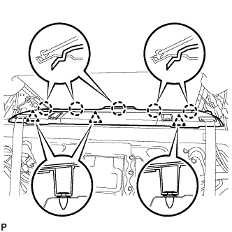
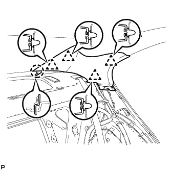
INSTALL ROOF HEADLINING ASSEMBLY (w/ Sliding Roof)
-
Place the roof headlining in the vehicle from the front right door.
-
Engage the hook, 10 claws, 8 fasteners and 2 clips, and install the roof headlining assembly.
-
Connect the roof wire connector and engage each clamp.
-
Connect each connector to the map light assembly.
-
-
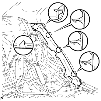
INSTALL ROOF HEADLINING ASSEMBLY (w/o Sliding Roof)
-
Place the roof headlining in the vehicle from the front right door.
-
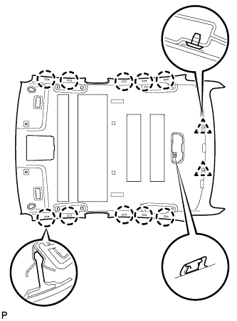
Engage the hook, 10 claws and 2 clips, and install the roof headlining assembly.
-
Connect the roof wire connector and engage each clamp.
-
Connect each connector to the map light assembly.
-
-
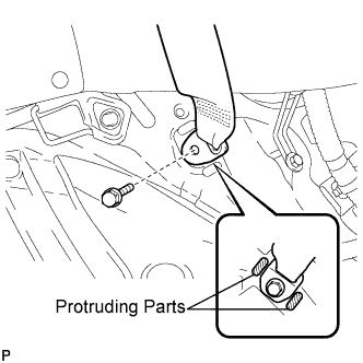
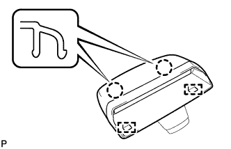
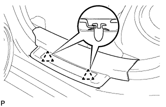
INSTALL ASSIST GRIP SUB-ASSEMBLY
-
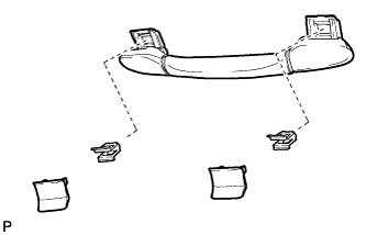
Put an assist grip sub-assembly together as shown in the illustration.
-
Install the assist grip sub-assembly.
Tech Tips
Use the same procedure for the other 3 assist grips.
-
-
INSTALL COAT HOOK
-
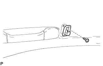
Install the coat hook with the screw.
Tech Tips
Use the same procedure to install the hook on the other side.
-
-
INSTALL SPOT LIGHT ASSEMBLY
-
Connect the connector.
-
Engage the 2 guides.
-
Engage the 2 clips and install the spot light assembly.
-
-
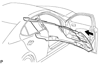
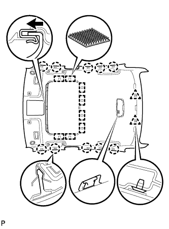
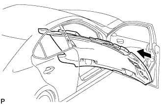
INSTALL PACKAGE TRAY TRIM PANEL ASSEMBLY
-
Pass the 2 rear seat belt floor anchors through the package tray trim panel assembly.
-
Engage the 3 clips and 5 claws to install the package tray trim panel assembly.
-
Engage the 4 claws to install the rear seat shoulder belt cover LH.
Tech Tips
Use the same procedures for the RH side and the LH side.
-
Install the floor end of the rear seat 3 point type belt assembly LH with the bolt.
- Torque:
- 42 N*m { 428 kgf*cm, 31 ft.*lbf }
Note
Do not allow the anchor part of the rear seat 3 point type belt assembly LH to overlap protruding parts of the floor panel.
Tech Tips
Use the same procedure for the RH side and the LH side.
-
Check if the ELR locks.
Note
The check should be performed with the outer belt assembly installed.
-
With the belt assembly installed, check that the belt locks when it is pulled out quickly.
-
-
-
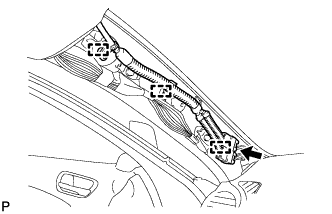
INSTALL CENTER STOP LIGHT SET
-
Connect the connector.
-
Engage the 2 guides.
-
Engage the 2 claws and install the center stop light set.
-
-
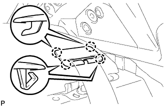
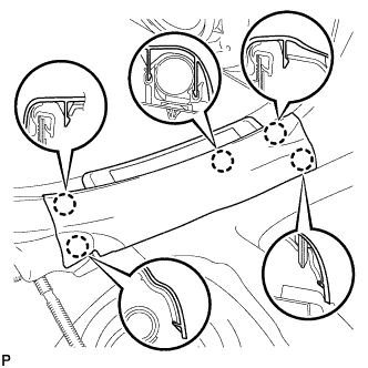
INSTALL ROOF SIDE INNER GARNISH LH
-
Engage the claw and 4 clips, and install the roof side garnish inner LH.
-
-
INSTALL ROOF SIDE INNER GARNISH RH
Tech Tips
Use the same procedure for the RH side and the LH side.
-
INSTALL REAR SEAT SIDE GARNISH LH
-
Engage the 5 claws and install the rear seat side garnish LH.
-
-
INSTALL REAR SEAT SIDE GARNISH RH
Tech Tips
Use the same procedure for the RH side and the LH side.
-
INSTALL REAR DOOR SCUFF PLATE LH
-
Engage the 2 clips.
-
Engage the 5 claws and install the rear door scuff plate LH.
-
-
INSTALL REAR DOOR SCUFF PLATE RH
Tech Tips
Use the same procedure for the RH side and the LH side.
-
INSTALL REAR SEATBACK ASSEMBLY
-
Place the seatback in the cabin.
Note
Be careful not to damage the vehicle body.
-
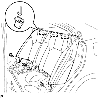
Engage the 3 hooks.
-
Install the rear seatback assembly with the 4 bolts.
- Torque:
- 18 N*m { 184 kgf*cm, 13 ft.*lbf }
-
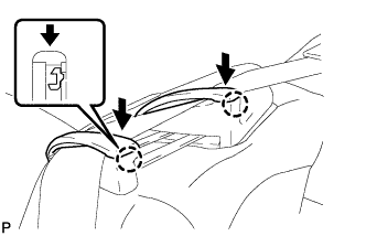
Pass the seat belt through the rear seat shoulder belt guide RH.
-
Engage the 2 claws and close the 2 caps of the rear seat shoulder belt guide RH.
-
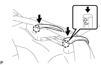
Pass the seat belt through the rear seat shoulder belt guide LH.
-
Engage the 2 claws and close the 2 caps of the rear seat shoulder belt guide LH.
-
-
INSTALL REAR SEAT CUSHION ASSEMBLY
-
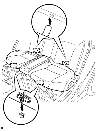
Engage the 2 rear hooks of the seat cushion to the child restraint seat anchor bracket.
-
Engage the 2 front hooks of the seat cushion to the vehicle body.
-
Confirm that the seat cushion is firmly installed.
Note
When installing the seat cushion, make sure the seat belt buckle is not under the seat cushion.
-
-
INSTALL REAR SEAT HEADREST ASSEMBLY LH
-
INSTALL REAR SEAT HEADREST ASSEMBLY RH