POWER WINDOW REGULATOR MOTOR (for Front Door) REMOVAL

-
DISCONNECT CABLE FROM NEGATIVE BATTERY TERMINAL
CAUTION:
Wait at least 90 seconds after disconnecting the cable from the negative (-) battery terminal to disable the SRS system Click here.
Note
When disconnecting the cable, some systems need to be initialized after the cable is reconnected Click here.
-
REMOVE FRONT DOOR INSIDE HANDLE BEZEL PLUG
-
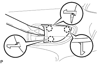
Using a moulding remover, disengage the 3 claws, and remove the front door inside handle bezel plug.
-
-
REMOVE POWER WINDOW REGULATOR MASTER SWITCH ASSEMBLY WITH FRONT DOOR ARMREST BASE PANEL
-
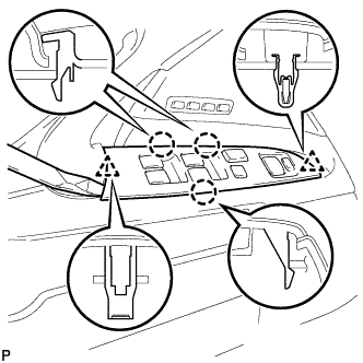
Using a moulding remover, disengage the 3 claws and the 2 clips.
-
Disconnect the connector and remove the power window regulator master switch assembly with front door armrest base panel.
-
-
REMOVE COURTESY LIGHT ASSEMBLY
-
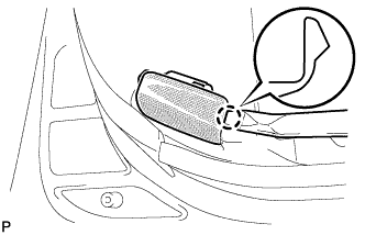
Using a moulding remover, disengage the claw and remove the courtesy light assembly.
-
Disconnect the connector.
-
-
REMOVE FRONT DOOR TRIM BOARD SUB-ASSEMBLY
-
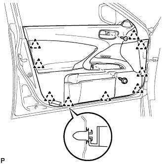
Remove the 2 screws.
-
Using a clip remover, disengage the 9 clips.
-
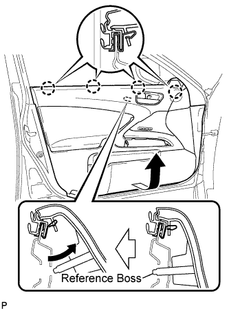
Pull out the front door trim board in the direction indicated by the arrow.
-
Remove the reference boss from the front door panel.
-
Raise the front door trim board to disengage the 4 claws and remove the front door trim board together with the front door inner glass weatherstrip.
-
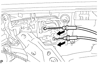
Disconnect the front door lock remote control cable assembly and front door inside locking cable assembly.
-
Disconnect each connector and remove the front door trim board sub-assembly.
-
Remove the 2 front door trim board retainers (green) from the front door trim board.
-
-
REMOVE FRONT DOOR INNER GLASS WEATHERSTRIP
-
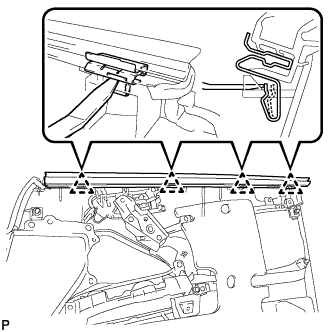
Using a moulding remover, disengage the 4 clips as shown in the illustration and remove the front door inner glass weatherstrip from the front door trim board.
-
-
REMOVE FRONT DOOR SERVICE HOLE COVER
-
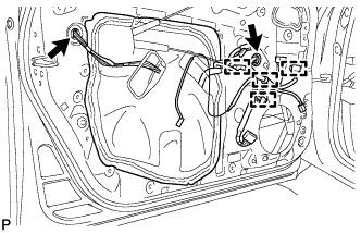
Disconnect each connector.
-
Disengage each clamp and remove the front door service hole cover.
Tech Tips
Remove any remaining butyl tape from the door.
-
-
REMOVE FRONT DOOR GLASS SUB-ASSEMBLY
-
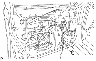
Remove the hole plug.
-
Connect the cable to the negative (-) battery terminal and front power window motors connector.
-
Connect the power window regulator master switch assembly and move the front door glass sub-assembly so that the door glass bolts can be seen.
-
Disconnect the power window regulator master switch assembly and front power window motors connector.
-
Disconnect the cable from the negative (-) battery terminal.
-
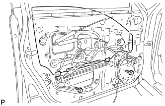
Remove the 2 bolts.
Note
After the bolts are removed, do not allow the door glass to fall.
-
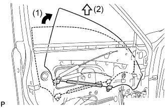
Remove the front door glass sub-assembly as shown in the illustration.
Note
Do not damage the door glass.
-
-
REMOVE FRONT DOOR WINDOW REGULATOR SUB-ASSEMBLY
-
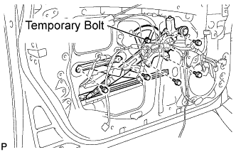
Loosen the temporary bolt.
Note
Do not remove the temporary bolt. If the temporary bolt is removed, the front door window regulator may fall and cause damage.
-
Remove the 5 bolts.
-
Remove the front door window regulator sub-assembly and the front power window regulator motor assembly as a unit.
-
Remove the temporary bolt from the front door window regulator sub-assembly.
-
-
REMOVE FRONT POWER WINDOW REGULATOR MOTOR
-
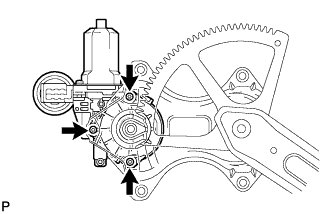
Using a "TORX" socket wrench (T25), remove the 3 screws and the front power window regulator motor.
-