POWER WINDOW CONTROL SYSTEM Front Passenger Side Power Window Auto Up / Down Function does not Operate with Front Passenger Side Power Window Switch
DESCRIPTION
-
If the pulse sensor on the front power window regulator motor assembly (for front passenger side) malfunctions, the regulator will enter fail-safe mode, and the auto up/down function will not operate.
-
If the power window initialization Click here has not been performed, the auto up/down function will not operate.
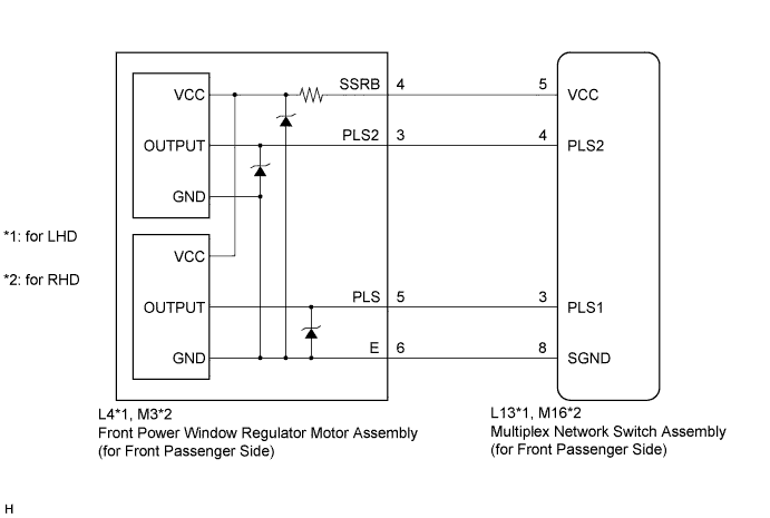
WIRING DIAGRAM
INSPECTION PROCEDURE
Note
-
When the front power window regulator motor assembly (for front passenger side) connector or the multiplex network switch assembly (for front passenger side) connector is disconnected, the power window control system must be initialized Click here.
-
Since the power window control system has functions that use multiplex communication, first confirm that there is no malfunction in the multiplex communication system by inspecting the multiplex communication functions in accordance with the How to Proceed with Troubleshooting procedures Click here. Then, conduct the following inspection procedure.
PROCEDURE
-
CHECK POWER WINDOW CONTROL SYSTEM (LED Illumination Check (for Front Passenger Side))
-
Turn the engine switch on (IG).
-
Operate the multiplex network switch assembly (for front passenger side) for 2 seconds or more.
-
Check the blinking pattern of the LED illumination. Compare the blinking pattern with the illustration below.
Tech Tips
If there is a malfunction in the pulse sensor, manually operating the multiplex network master switch assembly or multiplex network switch assembly will cause the multiplex network master switch assembly or multiplex network switch assembly LED illumination to blink. The LED illumination continues to blink for 45 seconds or until the engine switch is turned off. After 45 seconds, the multiplex network master switch assembly or multiplex network switch assembly LED illumination remains on.
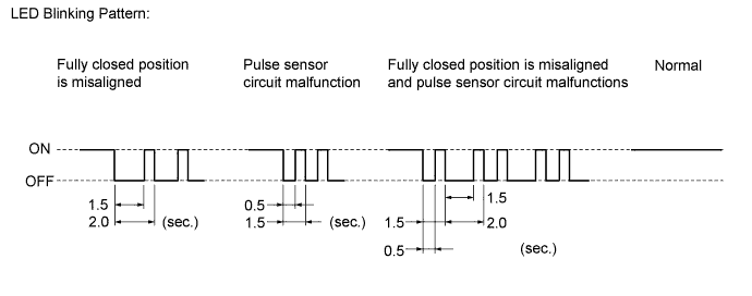
Result Result Proceed to Normal A Fully closed position is misaligned B Fully closed position is misaligned and pulse sensor circuit malfunctions Pulse sensor circuit malfunctions C
A 
REPLACE MULTIPLEX NETWORK SWITCH ASSEMBLY (for Front Passenger Side) Click here
B 
INSPECT MULTIPLEX NETWORK SWITCH ASSEMBLY (PULSE SENSOR POWER SOURCE (for Front Passenger Side)) Click here
C 
-
-
PERFORM INITIALIZATION (POWER WINDOW CONTROL SYSTEM (for Front Passenger Side))
-
Initialize the power window control system (for front passenger side) Click here.
NEXT
-
-
CHECK POWER WINDOW CONTROL SYSTEM (Front Passenger Side Auto Up/Down Function)
-
Check that the front passenger side auto up/down function operates normally Click here.
OK Front passenger side auto up/down function operates normally.
NG
INSPECT MULTIPLEX NETWORK SWITCH ASSEMBLY (PULSE SENSOR POWER SOURCE (for Front Passenger Side)) Click here
OK 
END (INITIALIZATION IS DEFECTIVE)
-
-
INSPECT MULTIPLEX NETWORK SWITCH ASSEMBLY (PULSE SENSOR POWER SOURCE (for Front Passenger Side))
-
Turn the engine switch on (IG).
-
Measure the voltage according to the value(s) in the table below.
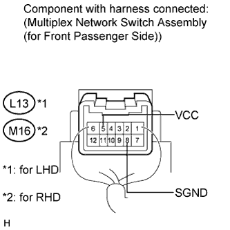
Standard Voltage for LHD Tester Connection Switch Condition Specified Condition L13-5 (VCC) - L13-8 (SGND) Front passenger side power window switch OFF Below 1 V L13-5 (VCC) - L13-8 (SGND) Front passenger side power window switch UP or DOWN 11 to 14 V for RHD Tester Connection Switch Condition Specified Condition M16-5 (VCC) - M16-8 (SGND) Front passenger side power window switch OFF Below 1 V M16-5 (VCC) - M16-8 (SGND) Front passenger side power window switch UP or DOWN 11 to 14 V
NG
REPLACE MULTIPLEX NETWORK SWITCH ASSEMBLY (for Front Passenger Side) Click here
OK
-
-
CHECK HARNESS AND CONNECTOR (SWITCH (for Front Passenger Side) - REGULATOR MOTOR)
-
Disconnect the front power window regulator motor assembly (for front passenger side) connector.
-
Disconnect the multiplex network assembly (for front passenger side) connector.
-
Measure the resistance according to the value(s) in the table below.
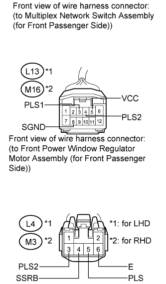
Standard Resistance for LHD Tester Connection Condition Specified Condition L13-3 (PLS1) - L4-5 (PLS) Always Below 1 Ω L13-4 (PLS2) - L4-3 (PLS2) Always Below 1 Ω L13-5 (VCC) - L4-4 (SSRB) Always Below 1 Ω L13-8 (SGND) - L4-6 (E) Always Below 1 Ω L13-3 (PLS1) - Body ground Always 10 kΩ or higher L13-4 (PLS2) - Body ground Always 10 kΩ or higher L13-5 (VCC) - Body ground Always 10 kΩ or higher L13-8 (SGND) - Body ground Always 10 kΩ or higher for RHD Tester Connection Condition Specified Condition M16-3 (PLS1) - M3-5 (PLS) Always Below 1 Ω M16-4 (PLS2) - M3-3 (PLS2) Always Below 1 Ω M16-5 (VCC) - M3-4 (SSRB) Always Below 1 Ω M16-8 (SGND) - M3-6 (E) Always Below 1 Ω M16-3 (PLS1) - Body ground Always 10 kΩ or higher M16-4 (PLS2) - Body ground Always 10 kΩ or higher M16-5 (VCC) - Body ground Always 10 kΩ or higher M16-8 (SGND) - Body ground Always 10 kΩ or higher
NG
REPAIR OR REPLACE HARNESS OR CONNECTOR
OK
-
-
REPLACE FRONT POWER WINDOW REGULATOR MOTOR ASSEMBLY (for Front Passenger Side)
-
Replace the front power window regulator motor assembly (for front passenger side) Click here.
NEXT
-
-
PERFORM INITIALIZATION (POWER WINDOW CONTROL SYSTEM (for Front Passenger Side))
-
Initialize the power window control system (for front passenger side) Click here.
NEXT
-
-
CHECK POWER WINDOW CONTROL SYSTEM (Front Passenger Side Auto Up/Down Function)
-
Check that the front passenger side auto up/down function operates normally Click here.
OK Front passenger side auto up/down function operates normally.
NG
REPLACE MULTIPLEX NETWORK SWITCH ASSEMBLY (for Front Passenger Side) Click here
OK
END (POWER WINDOW REGULATOR MOTOR IS DEFECTIVE)
-