POWER WINDOW CONTROL SYSTEM Rear Power Window RH does not Operate with Rear Power Window Switch RH
DESCRIPTION
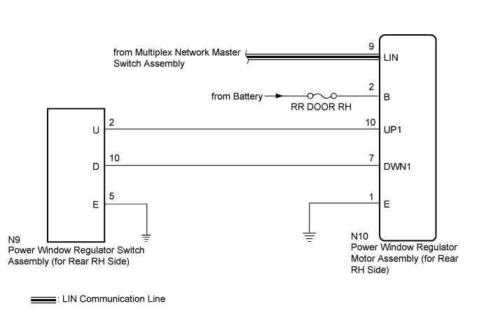
When the engine is running or the engine switch is on (IG), the power window regulator motor assembly (for rear RH side) is operated by the power window regulator switch assembly (for rear RH side). The power window regulator motor assembly (for rear RH side) has motor, regulator, and ECU functions.
Tech Tips
If the pulse sensor built into the power window regulator motor assembly (for rear RH side) malfunctions, the power window control system enters fail-safe mode. The remote up/down and auto up/down functions cannot be operated during fail-safe mode. However, the power window can be closed by holding the power window regulator switch assembly (for rear RH side) in the auto up position, and opened manually by pushing down the power window regulator switch assembly (for rear RH side).
WIRING DIAGRAM
INSPECTION PROCEDURE
Note
-
When the power window regulator motor assembly (for rear RH side) is reinstalled or replaced, the power window control system must be initialized.
-
After a door glass or a door glass run has been replaced, the jam protection function may operate unexpectedly when the auto up function is used. In such cases, the auto up function can be reinitialized by repeating the following operations at least 5 times:
-
Close the power window by fully pulling up the power window regulator switch assembly (for rear RH side) and holding it at the auto up position.
-
Open the power window by fully pushing down the power window regulator switch assembly (for rear RH side).
PROCEDURE
-
INSPECT POWER WINDOW REGULATOR SWITCH ASSEMBLY (for Rear RH Side)
-
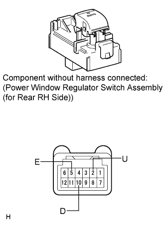
Remove the power window regulator switch assembly (for rear RH side) Click here.
-
Measure the resistance according to the value(s) in the table below.
Standard Resistance Tester Connection Switch Condition Specified Condition 2 (U) - 5 (E) Auto up or up position Below 1 Ω 10 (D) - 5 (E) Auto down or down position Below 1 Ω
NG 
REPLACE POWER WINDOW REGULATOR SWITCH ASSEMBLY (for Rear RH side) Click here
OK 
-
-
CHECK HARNESS AND CONNECTOR (REGULATOR MOTOR - BATTERY AND BODY GROUND)
-
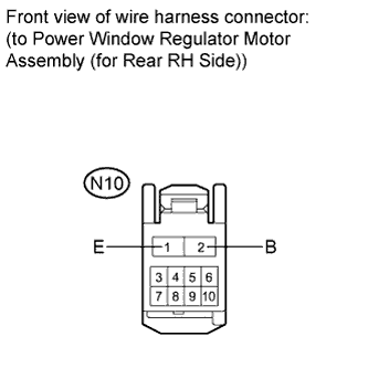
Measure the voltage according to the value(s) in the table below.
Standard Voltage Tester Connection Condition Specified Condition N10-2 (B) - Body ground Always 11 to 14 V -
Measure the resistance according to the value(s) in the table below.
Standard Resistance Tester Connection Condition Specified Condition N10-1 (E) - Body ground Always Below 1 Ω
NG
REPAIR OR REPLACE HARNESS OR CONNECTOR
OK
-
-
CHECK HARNESS AND CONNECTOR (REAR RH SIDE SWITCH - REAR RH SIDE MOTOR AND BODY GROUND)
-
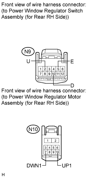
Disconnect the power window regulator motor assembly (for rear RH side) connector.
-
Measure the resistance according to the value(s) in the table below.
Standard Resistance Tester Connection Condition Specified Condition N9-2 (U) - N10-10 (UP1) Always Below 1 Ω N9-10 (D) - N10-7 (DWN1) Always Below 1 Ω N9-5 (E) - Body ground Always Below 1 Ω N9-2 (U) - Body ground Always 10 kΩ or higher N9-10 (D) - Body ground Always 10 kΩ or higher N10-10 (UP1) - Body ground Always 10 kΩ or higher N10-7 (DWN1) - Body ground Always 10 kΩ or higher
NG
REPAIR OR REPLACE HARNESS OR CONNECTOR
OK
-
-
REPLACE POWER WINDOW REGULATOR MOTOR ASSEMBLY (for Rear RH Side)
-
Replace the power window regulator motor assembly (for rear RH side) Click here.
NEXT
-
-
CHECK MANUAL UP / DOWN FUNCTION
-
Check that the rear RH side door power window moves when the manual up/down function of the power window regulator assembly (for rear RH side) is operated Click here.
OK Rear RH side manual up/down function is normal.
NG
REPLACE MULTIPLEX NETWORK MASTER SWITCH ASSEMBLY Click here
OK 
END (POWER WINDOW REGULATOR MOTOR ASSEMBLY IS DEFECTIVE)
-