POWER WINDOW CONTROL SYSTEM Rear Power Window RH does not Operate with Rear Power Window Switch RH
DESCRIPTION
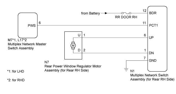
When the engine is running or the engine switch is on (IG) and window lock switch is OFF, the rear power window regulator motor assembly (for rear RH side) is driven by operating the multiplex network switch assembly (for rear RH side). The rear power window regulator motor assembly (for rear RH side) has motor, regulator, and sensor functions.
WIRING DIAGRAM
INSPECTION PROCEDURE
Note
-
When the rear power window regulator motor assembly (for rear RH side) connector, the multiplex network master switch assembly connector or the multiplex network switch assembly (for rear RH side) is disconnected, the power window control system must be initialized Click here.
-
Since the power window control system has functions that use multiplex communication, first confirm that there is no malfunction in the multiplex communication system by inspecting the multiplex communication functions in accordance with the How to Proceed with Troubleshooting procedures Click here. Then, conduct the following inspection procedure.
PROCEDURE
-
CHECK FUSE (RR DOOR RH)
-
Remove the RR DOOR RH fuse from the main body ECU RH (cowl side junction block RH).
-
Measure the resistance according to the value(s) in the table below.
Standard Resistance Tester Connection Condition Specified Condition RR DOOR RH fuse Always Below 1 Ω
NG 
REPLACE FUSE
OK 
-
-
CHECK POWER WINDOW CONTROL SYSTEM (Rear RH Side Remote Up/Down Function)
-
Check that the rear RH side remote up/down function operates normally Click here.
OK Rear RH side remote up/down function operates normally.
NG 
CHECK HARNESS AND CONNECTOR (SWITCH (for Rear RH Side) - BODY GROUND AND BATTERY) Click here
OK 
REPLACE MULTIPLEX NETWORK SWITCH ASSEMBLY (for Rear RH side) Click here
-
-
CHECK HARNESS AND CONNECTOR (SWITCH (for Rear RH Side) - BODY GROUND AND BATTERY)
-
Disconnect the multiplex network switch assembly (for rear RH side) connector.
-
Measure the resistance according to the value(s) in the table below.
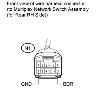
Standard Resistance Tester Connection Condition Specified Condition N1-7 (GND) - Body ground Always Below 1 Ω -
Measure the voltage according to the value(s) in the table below.
Standard Voltage Tester Connection Condition Specified Condition N1-12 (BDR) - N1-7 (GND) Always 11 to 14 V
NG
REPAIR OR REPLACE HARNESS OR CONNECTOR
OK
-
-
INSPECT MULTIPLEX NETWORK MASTER SWITCH ASSEMBLY (WINDOW LOCK SWITCH OPERATION SIGNAL)
-
Turn the engine switch on (IG).
-
Measure the voltage according to the value(s) in the table below.
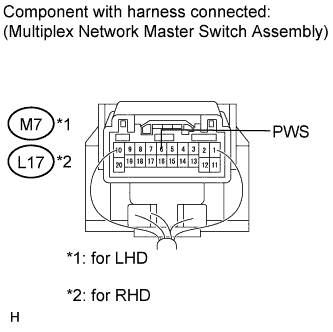
Standard Voltage for LHD Tester Connection Condition Specified Condition M7-6 (PWS) - Body ground Power window lock switch UNLOCK 11 to 14 V M7-6 (PWS) - Body ground Power window lock switch LOCK Below 1 V for RHD Tester Connection Condition Specified Condition L17-6 (PWS) - Body ground Power window lock switch UNLOCK 11 to 14 V L17-6 (PWS) - Body ground Power window lock switch LOCK Below 1 V
NG
REPLACE MULTIPLEX NETWORK MASTER SWITCH ASSEMBLY Click here
OK
-
-
CHECK HARNESS AND CONNECTOR (MASTER SWITCH - SWITCH (for Rear RH Side))
-
Disconnect the multiplex network master switch assembly connector.
-
Measure the resistance according to the value(s) in the table below.
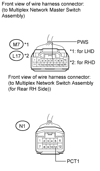
Standard Resistance for LHD Tester Connection Condition Specified Condition M7-6 (PWS) - N1-11 (PCT1) Always Below 1 Ω M7-6 (PWS) - Body ground Always 10 kΩ or higher for RHD Tester Connection Condition Specified Condition L17-6 (PWS) - N1-11 (PCT1) Always Below 1 Ω L17-6 (PWS) - Body ground Always 10 kΩ or higher
NG
REPAIR OR REPLACE HARNESS OR CONNECTOR
OK
-
-
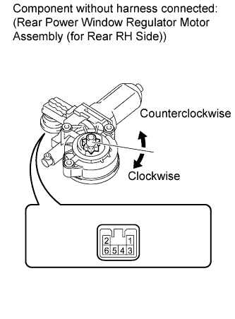
INSPECT REAR POWER WINDOW REGULATOR MOTOR ASSEMBLY (for Rear RH side)
-
Remove the rear power window regulator motor assembly (for rear RH side) Click here.
-
Check power window regulator motor operation:
-
Apply battery voltage to connector terminals 1 and 2.
Note
Do not apply battery voltage to any terminals except terminals 1 and 2.
-
Check that the motor gear rotates smoothly as follows.
OK Measurement Condition Specified Condition Battery positive (+) → 1
Battery negative (-) → 2
Motor gear rotates counterclockwise Battery positive (+) → 2
Battery negative (-) → 1
Motor gear rotates clockwise
-
-
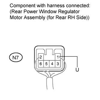
Check PTC operation:
Note
This check must be performed with the power window regulator and door glass installed on the vehicle.
-
Install the rear power window regulator motor assembly (for rear RH side) Click here.
-
Connect an electrical tester DC 400 A probe to the wire harness of terminal 1.
Note
Match the arrow mark of the probe with the direction of the current flow.
-
Fully close the door glass by pulling up the multiplex network switch assembly (for rear RH side). Wait for approximately 60 seconds.
-
Continue to pull up the multiplex network switch assembly (for rear RH side) and measure how long it takes for the electrical current to change from a range of 16 to 28 A to approximately 1 A (current shut-off inspection).
Standard 4 to 90 seconds -
Wait for 60 seconds after the previous step, and then push down the multiplex network switch assembly (for rear RH side).
OK The rear RH side window goes down.
-
NG
REPLACE REAR POWER WINDOW REGULATOR MOTOR ASSEMBLY (for Rear RH Side) Click here
OK
-
-
CHECK HARNESS AND CONNECTOR (SWITCH (for Rear RH Side) - REGULATOR MOTOR)
-
Disconnect the front power window regulator motor assembly (for rear RH side) connector.
-
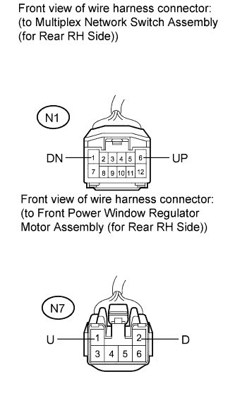
Measure the resistance according to the value(s) in the table below.
Standard Resistance Tester Connection Condition Specified Condition N1-6 (UP) - N7-1 (U) Always Below 1 Ω N1-1 (DN) - N7-2 (D) Always Below 1 Ω N1-6 (UP) - Body ground Always 10 kΩ or higher N1-1 (DN) - Body ground Always 10 kΩ or higher
NG
REPAIR OR REPLACE HARNESS OR CONNECTOR
OK
REPLACE MULTIPLEX NETWORK SWITCH ASSEMBLY (for Rear RH side) Click here
-