POWER WINDOW CONTROL SYSTEM TERMINALS OF ECU

-
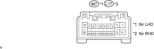
CHECK MULTIPLEX NETWORK MASTER SWITCH ASSEMBLY
-
Disconnect the M7*1 or L17*2 multiplex network master switch assembly connector.
-
*1: for LHD
-
*2: for RHD
-
-
Measure the voltage and resistance according to the value(s) in the table below.
for LHD Tester Connection Wiring Color Terminal Description Condition Specified Condition M7-2 (GND) - Body ground W-B - Body ground Ground Always Below 1 Ω M7-4 (KL) - M7-2 (GND) L - W-B Key linked power window lock signal Using key, operate driver door lock cylinder to FREE 10 kΩ or higher M7-4 (KL) - M7-2 (GND) L - W-B Key linked power window lock signal Using key, operate driver door lock cylinder to LOCK Below 1 Ω M7-9 (CPUB) - M7-2 (GND) G - W-B +B power supply Always 11 to 14 V M7-10 (BDR) - M7-2 (GND) L - W-B +B power supply Always 11 to 14 V M7-14 (KUL) - M7-2 (GND) W - W-B Key linked power window unlock signal Using key, operate driver door lock cylinder to FREE 10 kΩ or higher M7-14 (KUL) - M7-2 (GND) W - W-B Key linked power window unlock signal Using key, operate driver door lock cylinder to UNLOCK Below 1 Ω M7-20 (SIG) - M7-2 (GND) B - W-B Ignition power supply Engine switch off Below 1 V M7-20 (SIG) - M7-2 (GND) B - W-B Ignition power supply Engine switch on (IG) 11 to 14 V for RHD Tester Connection Wiring Color Terminal Description Condition Specified Condition L17-2 (GND) - Body ground W-B - Body ground Ground Always Below 1 Ω L17-4 (KL) - L17-2 (GND) L - W-B Key linked power window lock signal Using key, operate driver door lock cylinder to FREE 10 kΩ or higher L17-4 (KL) - L17-2 (GND) L - W-B Key linked power window lock signal Using key, operate driver door lock cylinder to LOCK Below 1 Ω L17-9 (CPUB) - L17-2 (GND) G - W-B +B power supply Always 11 to 14 V L17-10 (BDR) - L17-2 (GND) L - W-B +B power supply Always 11 to 14 V L17-14 (KUL) - L17-2 (GND) W - W-B Key linked power window unlock signal Using key, operate driver door lock cylinder to FREE 10 kΩ or higher L17-14 (KUL) - L17-2 (GND) W - W-B Key linked power window unlock signal Using key, operate driver door lock cylinder to UNLOCK Below 1 Ω L17-20 (SIG) - L17-2 (GND) B - W-B Ignition power supply Engine switch off Below 1 V L17-20 (SIG) - L17-2 (GND) B - W-B Ignition power supply Engine switch on (IG) 11 to 14 V If the result is not as specified, there may be a malfunction on the wire harness side.
-
Reconnect the M7*1 or L17*2 multiplex network master switch assembly connector.
-
*1: for LHD
-
*2: for RHD
-
-
Reset the power window regulator motor Click here.
-
Measure the voltage according to the value(s) in the table below.
for LHD Tester Connection Wiring Color Terminal Description Condition Specified Condition M7-1 (UP) - M7-2 (GND) R - W-B Power window motor UP output Engine switch on (IG), driver side power window switch OFF Below 1 V M7-1 (UP) - M7-2 (GND) R - W-B Power window motor UP output Engine switch on (IG), driver side power window switch UP (Manual operation) 11 to 14 V M7-1 (UP) - M7-2 (GND) R - W-B Power window motor UP output Engine switch on (IG), driver side power window fully open Below 1 V M7-1 (UP) - M7-2 (GND) R - W-B Power window motor UP output Engine switch on (IG), driver side power window switch UP (Auto operation) 11 to 14 V M7-1 (UP) - M7-2 (GND) R - W-B Power window motor UP output Engine switch on (IG), driver side power window fully closed Below 1 V M7-4 (KL) - M7-2 (GND) L - W-B Key linked power window lock signal Using key, operate driver door lock cylinder to FREE 11 to 14 V M7-4 (KL) - M7-2 (GND) L - W-B Key linked power window lock signal Using key, operate driver door lock cylinder to LOCK Below 1 V M7-6 (PWS) - M7-2 (GND) P - W-B Power window lock switch output Engine switch on (IG), power window lock switch UNLOCK 11 to 14 V M7-6 (PWS) - M7-2 (GND) P - W-B Power window lock switch output Engine switch on (IG), power window lock switch LOCK Below 1 V M7-14 (KUL) - M7-2 (GND) W - W-B Key linked power window unlock signal Using key, operate driver door lock cylinder to FREE 11 to 14 V M7-14 (KUL) - M7-2 (GND) W - W-B Key linked power window unlock signal Using key, operate driver door lock cylinder to UNLOCK Below 1 V M7-11 (DN) - M7-2 (GND) G - W-B Power window motor DOWN output Engine switch on (IG), driver side power window switch OFF Below 1 V M7-11 (DN) - M7-2 (GND) G - W-B Power window motor DOWN output Engine switch on (IG), driver side power window switch DOWN (Manual operation) 11 to 14 V M7-11 (DN) - M7-2 (GND) G - W-B Power window motor DOWN output Engine switch on (IG), driver side power window fully closed Below 1 V M7-11 (DN) - M7-2 (GND) G - W-B Power window motor DOWN output Engine switch on (IG), driver side power window switch DOWN (Auto operation) 11 to 14 V M7-11 (DN) - M7-2 (GND) G - W-B Power window motor DOWN output Engine switch on (IG), driver side power window fully open Below 1 V M7-19 (VCC) - M7-2 (GND) LG - W-B Power window motor power source Engine switch on (IG), driver side power window switch OFF Below 1 V M7-19 (VCC) - M7-2 (GND) LG - W-B Power window motor power source Engine switch on (IG), driver side power window switch UP or DOWN 11 to 14 V for RHD Tester Connection Wiring Color Terminal Description Condition Specified Condition L17-1 (UP) - L17-2 (GND) R - W-B Power window motor UP output Engine switch on (IG), driver side power window switch OFF Below 1 V L17-1 (UP) - L17-2 (GND) R - W-B Power window motor UP output Engine switch on (IG), driver side power window switch UP (Manual operation) 11 to 14 V L17-1 (UP) - L17-2 (GND) R - W-B Power window motor UP output Engine switch on (IG), driver side power window fully open Below 1 V L17-1 (UP) - L17-2 (GND) R - W-B Power window motor UP output Engine switch on (IG), driver side power window switch UP (Auto operation) 11 to 14 V L17-1 (UP) - L17-2 (GND) R - W-B Power window motor UP output Engine switch on (IG), driver side power window fully closed Below 1 V L17-4 (KL) - L17-2 (GND) L - W-B Key linked power window lock signal Using key, operate driver door lock cylinder to FREE 11 to 14 V L17-4 (KL) - L17-2 (GND) L - W-B Key linked power window lock signal Using key, operate driver door lock cylinder to LOCK Below 1 V L17-6 (PWS) - L17-2 (GND) P - W-B Power window lock switch output Engine switch on (IG), power window lock switch UNLOCK 11 to 14 V L17-6 (PWS) - L17-2 (GND) P - W-B Power window lock switch output Engine switch on (IG), power window lock switch LOCK Below 1 V L17-14 (KUL) - L17-2 (GND) W - W-B Key linked power window unlock signal Using key, operate driver door lock cylinder to FREE 11 to 14 V L17-14 (KUL) - L17-2 (GND) W - W-B Key linked power window unlock signal Using key, operate driver door lock cylinder to UNLOCK Below 1 V L17-11 (DN) - L17-2 (GND) G - W-B Power window motor DOWN output Engine switch on (IG), driver side power window switch OFF Below 1 V L17-11 (DN) - L17-2 (GND) G - W-B Power window motor DOWN output Engine switch on (IG), driver side power window switch DOWN (Manual operation) 11 to 14 V L17-11 (DN) - L17-2 (GND) G - W-B Power window motor DOWN output Engine switch on (IG), driver side power window fully closed Below 1 V L17-11 (DN) - L17-2 (GND) G - W-B Power window motor DOWN output Engine switch on (IG), driver side power window switch DOWN (Auto operation) 11 to 14 V L17-11 (DN) - L17-2 (GND) G - W-B Power window motor DOWN output Engine switch on (IG), driver side power window fully open Below 1 V L17-19 (VCC) - L17-2 (GND) LG - W-B Power window motor power source Engine switch on (IG), driver side power window switch OFF Below 1 V L17-19 (VCC) - L17-2 (GND) LG - W-B Power window motor power source Engine switch on (IG), driver side power window switch UP or DOWN 11 to 14 V If the result is not as specified, the multiplex network master switch assembly may have a malfunction.
-
-
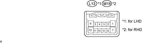
CHECK MULTIPLEX NETWORK SWITCH ASSEMBLY (for Front Passenger Side)
-
Disconnect the L13*1 or M16*2 multiplex network switch assembly connector.
-
*1: for LHD
-
*2: for RHD
-
-
Measure the voltage and resistance according to the value(s) in the table below.
for LHD Tester Connection Wiring Color Terminal Description Condition Specified Condition L13-7 (GND) - Body ground W-B - Body ground Ground Always Below 1 Ω L13-12 (BDR) - L13-7 (GND) L - W-B +B power supply Always 11 to 14 V for RHD Tester Connection Wiring Color Terminal Description Condition Specified Condition M16-7 (GND) - Body ground W-B - Body ground Ground Always Below 1 Ω M16-12 (BDR) - M16-7 (GND) L - W-B +B power supply Always 11 to 14 V If the result is not as specified, there may be a malfunction on the wire harness side.
-
Reconnect the L13*1 or M16*2 multiplex network switch assembly connector.
-
*1: for LHD
-
*2: for RHD
-
-
Reset the power window regulator motor Click here.
-
Measure the voltage according to the value(s) in the table below.
for LHD Tester Connection Wiring Color Terminal Description Condition Specified Condition L13-1 (DN) - L13-7 (GND) G - W-B Power window motor DOWN output Engine switch on (IG), front passenger side power window switch OFF Below 1 V L13-1 (DN) - L13-7 (GND) G - W-B Power window motor DOWN output Engine switch on (IG), front passenger side power window switch DOWN (Manual operation) 11 to 14 V L13-1 (DN) - L13-7 (GND) G - W-B Power window motor DOWN output Engine switch on (IG), front passenger side power window fully closed Below 1 V L13-1 (DN) - L13-7 (GND) G - W-B Power window motor DOWN output Engine switch on (IG), front passenger side power window switch DOWN (Auto operation) 11 to 14 V L13-1 (DN) - L13-7 (GND) G - W-B Power window motor DOWN output Engine switch on (IG), front passenger side power window fully open Below 1 V L13-5 (VCC) - L13-8 (SGND) W - L Power window motor power source Engine switch on (IG), front passenger side power window switch OFF Below 1 V L13-5 (VCC) - L13-8 (SGND) W - L Power window motor power source Engine switch on (IG), front passenger side power window switch UP or DOWN 11 to 14 V L13-6 (UP) - L13-7 (GND) R - W-B Power window motor UP output Engine switch on (IG), front passenger side power window switch OFF Below 1 V L13-6 (UP) - L13-7 (GND) R - W-B Power window motor UP output Engine switch on (IG), front passenger side power window switch UP (Manual operation) 11 to 14 V L13-6 (UP) - L13-7 (GND) R - W-B Power window motor UP output Engine switch on (IG), front passenger side power window fully open Below 1 V L13-6 (UP) - L13-7 (GND) R - W-B Power window motor UP output Engine switch on (IG), front passenger side power window UP (Auto operation) 11 to 14 V L13-6 (UP) - L13-7 (GND) R - W-B Power window motor UP output Engine switch on (IG), front passenger side power window fully closed Below 1 V L13-11 (PCT) - L13-7 (GND) P - W-B Power window lock switch output Engine switch on (IG), power window lock switch UNLOCK 11 to 14 V L13-11 (PCT) - L13-7 (GND) P - W-B Power window lock switch output Engine switch on (IG), power window lock switch LOCK Below 1 V for RHD Tester Connection Wiring Color Terminal Description Condition Specified Condition M16-1 (DN) - M16-7 (GND) LG - W-B Power window motor DOWN output Engine switch on (IG), front passenger side power window switch OFF Below 1 V M16-1 (DN) - M16-7 (GND) LG - W-B Power window motor DOWN output Engine switch on (IG), front passenger side power window switch DOWN (Manual operation) 11 to 14 V M16-1 (DN) - M16-7 (GND) LG - W-B Power window motor DOWN output Engine switch on (IG), front passenger side power window fully closed Below 1 V M16-1 (DN) - M16-7 (GND) LG - W-B Power window motor DOWN output Engine switch on (IG), front passenger side power window switch DOWN (Auto operation) 11 to 14 V M16-1 (DN) - M16-7 (GND) LG - W-B Power window motor DOWN output Engine switch on (IG), front passenger side power window fully open Below 1 V M16-5 (VCC) - M16-8 (SGND) W - R Power window motor power source Engine switch on (IG), front passenger side power window switch OFF Below 1 V M16-5 (VCC) - M16-8 (SGND) W - R Power window motor power source Engine switch on (IG), front passenger side power window switch UP or DOWN 11 to 14 V M16-6 (UP) - M16-7 (GND) R - W-B Power window motor UP output Engine switch on (IG), front passenger side power window switch OFF Below 1 V M16-6 (UP) - M16-7 (GND) R - W-B Power window motor UP output Engine switch on (IG), front passenger side power window switch UP (Manual operation) 11 to 14 V M16-6 (UP) - M16-7 (GND) R - W-B Power window motor UP output Engine switch on (IG), front passenger side power window fully open Below 1 V M16-6 (UP) - M16-7 (GND) R - W-B Power window motor UP output Engine switch on (IG), front passenger side power window UP (Auto operation) 11 to 14 V M16-6 (UP) - M16-7 (GND) R - W-B Power window motor UP output Engine switch on (IG), front passenger side power window fully closed Below 1 V M16-11 (PCT) - M16-7 (GND) P - W-B Power window lock switch output Engine switch on (IG), power window lock switch UNLOCK 11 to 14 V M16-11 (PCT) - M16-7 (GND) P - W-B Power window lock switch output Engine switch on (IG), power window lock switch LOCK Below 1 V If the result is not as specified, the multiplex network switch assembly may have a malfunction.
-
-
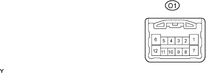
CHECK MULTIPLEX NETWORK SWITCH ASSEMBLY (REAR LH)
-
Disconnect the O1 multiplex network switch assembly connector.
-
Measure the voltage and resistance according to the value(s) in the table below.
Tester Connection Wiring Color Terminal Description Condition Specified Condition O1-7 (GND) - Body ground W-B - Body ground Ground Always Below 1 Ω O1-10 (SEL2) - O1-7 (GND) W-B - W-B Rear LH side detection signal Always Below 1 Ω O1-12 (BDR) - O1-7 (GND) O - W-B +B power supply Always 11 to 14 V If the result is not as specified, there may be a malfunction on the wire harness side.
-
Reconnect the O1 multiplex network switch assembly connector.
-
Reset the power window regulator motor Click here.
-
Measure the voltage according to the value(s) in the table below.
Tester Connection Wiring Color Terminal Description Condition Specified Condition O1-1 (DN) - O1-7 (GND) G - W-B Power window motor DOWN output Engine switch on (IG), rear LH power window switch OFF Below 1 V O1-1 (DN) - O1-7 (GND) G - W-B Power window motor DOWN output Engine switch on (IG), rear LH power window switch DOWN (Manual operation) 11 to 14 V O1-1 (DN) - O1-7 (GND) G - W-B Power window motor DOWN output Engine switch on (IG), rear LH power window fully closed Below 1 V O1-1 (DN) - O1-7 (GND) G - W-B Power window motor DOWN output Engine switch on (IG), rear LH power window switch DOWN (Auto operation) 11 to 14 V O1-1 (DN) - O1-7 (GND) G - W-B Power window motor DOWN output Engine switch on (IG), rear LH power window fully open Below 1 V O1-5 (VCC) - O1-8 (SGND) W - LG Power window motor power source Engine switch on (IG), rear LH side power window switch OFF Below 1 V O1-5 (VCC) - O1-8 (SGND) W - LG Power window motor power source Engine switch on (IG), rear LH side power window switch UP or DOWN 11 to 14 V O1-6 (UP) - O1-7 (GND) R - W-B Power window motor UP output Engine switch on (IG), rear LH power window switch OFF Below 1 V O1-6 (UP) - O1-7 (GND) R - W-B Power window motor UP output Engine switch on (IG), rear LH power window switch UP (Manual operation) 11 to 14 V O1-6 (UP) - O1-7 (GND) R - W-B Power window motor UP output Engine switch on (IG), rear LH power window fully open Below 1 V O1-6 (UP) - O1-7 (GND) R - W-B Power window motor UP output Engine switch on (IG), rear LH power window switch UP (Auto operation) 11 to 14 V O1-6 (UP) - O1-7 (GND) R - W-B Power window motor UP output Engine switch on (IG), rear LH power window fully closed Below 1 V O1-11 (PCT1) - O1-7 (GND) V - W-B Power window lock switch output Engine switch on (IG), power window lock switch UNLOCK 11 to 14 V O1-11 (PCT1) - O1-7 (GND) V - W-B Power window lock switch output Engine switch on (IG), power window lock switch LOCK Below 1 V If the result is not as specified, the multiplex network switch assembly may have a malfunction.
-
-
CHECK MULTIPLEX NETWORK SWITCH ASSEMBLY (REAR RH)
-
Disconnect the N1 multiplex network switch assembly connector.

-
Measure the voltage and resistance according to the value(s) in the table below.
Tester Connection Wiring Color Terminal Description Condition Specified Condition N1-7 (GND) - Body ground W-B - Body ground Ground Always Below 1 Ω N1-9 (SEL1) - N1-7 (GND) W-B - W-B Rear RH side detection signal Always Below 1 Ω N1-12 (BDR) - N1-7 (GND) O - W-B +B power supply Always 11 to 14 V If the result is not as specified, there may be a malfunction on the wire harness side.
-
Reconnect the N1 multiplex network switch assembly connector.
-
Reset the power window regulator motor Click here.
-
Measure the voltage according to the value(s) in the table below.
Tester Connection Wiring Color Terminal Description Condition Specified Condition N1-1 (DN) - N1-7 (GND) G - W-B Power window motor DOWN output Engine switch on (IG), rear RH power window switch OFF Below 1 V N1-1 (DN) - N1-7 (GND) G - W-B Power window motor DOWN output Engine switch on (IG), rear RH power window switch DOWN (Manual operation) 11 to 14 V N1-1 (DN) - N1-7 (GND) G - W-B Power window motor DOWN output Engine switch on (IG), rear RH power window fully closed Below 1 V N1-1 (DN) - N1-7 (GND) G - W-B Power window motor DOWN output Engine switch on (IG), rear RH power window switch DOWN (Auto operation) 11 to 14 V N1-1 (DN) - N1-7 (GND) G - W-B Power window motor DOWN output Engine switch on (IG), rear RH power window fully open Below 1 V N1-5 (VCC) - N1-8 (SGND) W - LG Power window motor power source Engine switch on (IG), rear RH side power window switch OFF Below 1 V N1-5 (VCC) - N1-8 (SGND) W - LG Power window motor power source Engine switch on (IG), rear RH side power window switch UP or DOWN 11 to 14 V N1-6 (UP) - N1-7 (GND) R - W-B Power window motor UP output Engine switch on (IG), rear RH power window switch OFF Below 1 V N1-6 (UP) - N1-7 (GND) R - W-B Power window motor UP output Engine switch on (IG), rear RH power window switch UP (Manual operation) 11 to 14 V N1-6 (UP) - N1-7 (GND) R - W-B Power window motor UP output Engine switch on (IG), rear RH power window fully open Below 1 V N1-6 (UP) - N1-7 (GND) R - W-B Power window motor UP output Engine switch on (IG), rear RH power window switch UP (Auto operation) 11 to 14 V N1-6 (UP) - N1-7 (GND) R - W-B Power window motor UP output Engine switch on (IG), rear RH power window fully closed Below 1 V N1-11 (PCT1) - N1-7 (GND) P - W-B Power window lock switch output Engine switch on (IG), power window lock switch UNLOCK 11 to 14 V N1-11 (PCT1) - N1-7 (GND) P - W-B Power window lock switch output Engine switch on (IG), power window lock switch LOCK 11 to 14 V If the result is not as specified, the multiplex network switch assembly may have a malfunction.
-
-
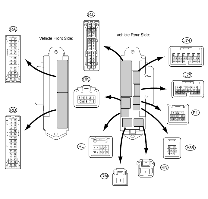
CHECK MAIN BODY ECU RH (COWL SIDE JUNCTION BLOCK RH)
-
Disconnect the RK, RN and RD cowl side junction block RH connectors.
-
Measure the voltage and resistance according to the value(s) in the table below.
Tester Connection Wiring Color Terminal Description Condition Specified Condition RK-5 (BECU) - Body ground G-R - Body ground Battery power supply Always 11 to 14 V RN-1 (BATB) - Body ground R - Body ground Battery power supply Always 11 to 14 V RD-7 (GND2) - Body ground W-B - Body ground Ground Always Below 1 Ω RD-17 (GND1) - Body ground W-B - Body ground Ground Always Below 1 Ω If the result is not as specified, there may be a malfunction in the wire harness side.
-
Reconnect the RK, RN, and RD cowl side junction block RH connectors.
-
Measure the voltage according to the value(s) in the table below.
Tester Connection Wiring Color Terminal Description Condition Specified Condition P1-14 (DCTY) - Body ground W - Body ground Driver side door courtesy switch input Driver side door open Below 1 V P1-14 (DCTY) - Body ground W - Body ground Driver side door courtesy switch input Driver side door closed 11 to 14 V J75-23 (PCTY) - Body ground B - Body ground*1
V - Body ground*2
Front passenger side door courtesy switch input Front passenger side door open Below 1 V J75-23 (PCTY) - Body ground B - Body ground*1
V - Body ground*2
Front passenger side door courtesy switch input Front passenger side door closed 11 to 14 V RA-11 (LCTY) - Body ground BR - Body ground Rear door LH courtesy light switch input Rear door LH open Below 1 V RA-11 (LCTY) - Body ground BR - Body ground Rear door LH courtesy light switch input Rear LH side door closed 11 to 14 V P1-16 (RCTY) - Body ground O - Body ground Rear door RH courtesy light switch input Rear door RH open Below 1 V P1-16 (RCTY) - Body ground O - Body ground Rear door RH courtesy light switch input Rear RH side door closed 11 to 14 V J75-25 (LGCY) - Body ground L - Body ground Luggage compartment door courtesy light switch input Luggage compartment door open Below 1 V J75-25 (LGCY) - Body ground L - Body ground Luggage compartment door courtesy light switch input Luggage compartment door closed 11 to 14 V
-
*1: for LHD
-
*2: for RHD
If the result is not as specified, the main body ECU RH (cowl side junction block RH) may have a malfunction.
-
-