POWER WINDOW CONTROL SYSTEM Remote Up / Down Function does not Operate
DESCRIPTION
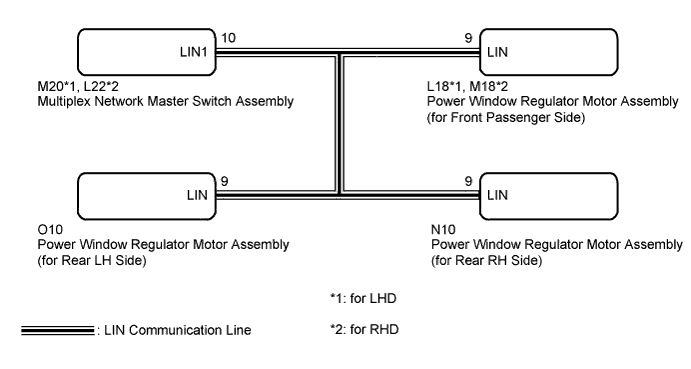
When the engine switch is on (IG), the multiplex network master switch assembly sends remote up/down signals to each power window regulator motor assembly via the LIN communication line.
WIRING DIAGRAM
INSPECTION PROCEDURE
PROCEDURE
-
READ VALUE USING INTELLIGENT TESTER (Master Switch)
-
Connect the intelligent tester to the DLC3.
-
Turn the engine switch on (IG).
-
Turn the intelligent tester on.
-
Enter the following menus: Body / Master Switch / Data List.
-
Read the Data List according to the display on the intelligent tester.
Master Switch (Multiplex Network Master Switch Assembly) Tester Display Measurement Item/Range Normal Condition Diagnostic Note P Door P/W Auto SW Front passenger side power window auto up/down switch signal / ON or OFF ON: Front passenger door power window auto switch operated
OFF: Front passenger door power window auto switch not operated
- RL Door P/W Auto SW Rear LH side power window auto up/down switch signal / ON or OFF ON: Rear LH power window auto switch operated
OFF: Rear LH power window auto switch not operated
- RR Door P/W Auto SW Rear RH side power window auto up/down switch signal / ON or OFF ON: Rear RH power window auto switch operated
OFF: Rear RH power window auto switch not operated
- P Door P/W Up SW Front passenger side power window manual up switch signal / ON or OFF ON: Front passenger door power window manual up switch operated
OFF: Front passenger door power window manual up switch not operated
- RL Door P/W Up SW Rear LH side power window manual up switch signal / ON or OFF ON: Rear LH power window manual up switch operated
OFF: Rear LH power window manual up switch not operated
- RR Door P/W Up SW Rear RH side power window manual up switch signal / ON or OFF ON: Rear RH power window manual up switch operated
OFF: Rear RH power window manual up switch not operated
- P Door P/W Down SW Front passenger side power window manual down switch signal / ON or OFF ON: Front passenger door power window manual down switch operated
OFF: Front passenger door power window manual down switch not operated
- RL Door P/W Down SW Rear LH side power window manual down switch signal / ON or OFF ON: Rear LH power window manual down switch operated
OFF: Rear LH power window manual down switch not operated
- RR Door P/W Down SW Rear RH side power window manual down switch signal / ON or OFF ON: Rear RH power window manual down switch operated
OFF: Rear RH power window manual down switch not operated
- Window Lock Switch Status Window lock switch signal / ON or OFF ON: Window lock switch LOCK position
OFF: Window lock switch UNLOCK position
- OK On the intelligent tester screen, ON or OFF is displayed accordingly.
NG 
REPLACE MULTIPLEX NETWORK MASTER SWITCH ASSEMBLY Click here
OK 
-
-
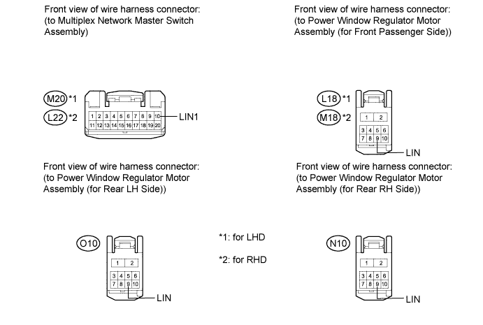
CHECK HARNESS AND CONNECTOR (LIN COMMUNICATION LINE)
-
Disconnect the multiplex network master switch assembly connector.
-
Disconnect the power window regulator motor assembly (for front passenger side, rear LH side and rear RH side) connectors.
-
Measure the resistance according to the value(s) in the table below.
Standard Resistance for Front Passenger Side Tester Connection Condition Specified Condition M20-10 (LIN1) - L18-9 (LIN)*1
L22-10 (LIN1) - M18-9 (LIN)*2
Always Below 1 Ω for Rear LH Side Tester Connection Condition Specified Condition M20-10 (LIN1) - O10-9 (LIN)*1
L22-10 (LIN1) - O10-9 (LIN)*2
Always Below 1 Ω for Rear RH Side Tester Connection Condition Specified Condition M20-10 (LIN1) - N10-9 (LIN)*1
L22-10 (LIN1) - N10-9 (LIN)*2
Always Below 1 Ω
-
*1: for LHD
-
*2: for RHD
-
NG
REPAIR OR REPLACE HARNESS OR CONNECTOR
OK
-
-
REPLACE MULTIPLEX NETWORK MASTER SWITCH ASSEMBLY
-
Replace the multiplex network master switch assembly Click here.
NEXT
-
-
CHECK REMOTE UP / DOWN FUNCTION
-
Check that the remote up/down function using the multiplex network master switch assembly operates the power windows Click here.
OK Remote up/down function is normal. Result Result Proceed to OK A NG (Front passenger side power window remote up / down function does not operate) B NG (Rear LH side power window remote up / down function does not operate) C NG (Rear RH side power window remote up / down function does not operate) D
B
REPLACE POWER WINDOW REGULATOR MOTOR ASSEMBLY (for Front Passenger Side) Click here
C
REPLACE POWER WINDOW REGULATOR MOTOR ASSEMBLY (for Rear RH Side) Click here
D
REPLACE POWER WINDOW REGULATOR MOTOR ASSEMBLY (for Rear LH Side) Click here
A 
END (MULTIPLEX NETWORK MASTER SWITCH ASSEMBLY IS DEFECTIVE)
-