POWER WINDOW CONTROL SYSTEM Remote Up / Down Function does not Operate
DESCRIPTION
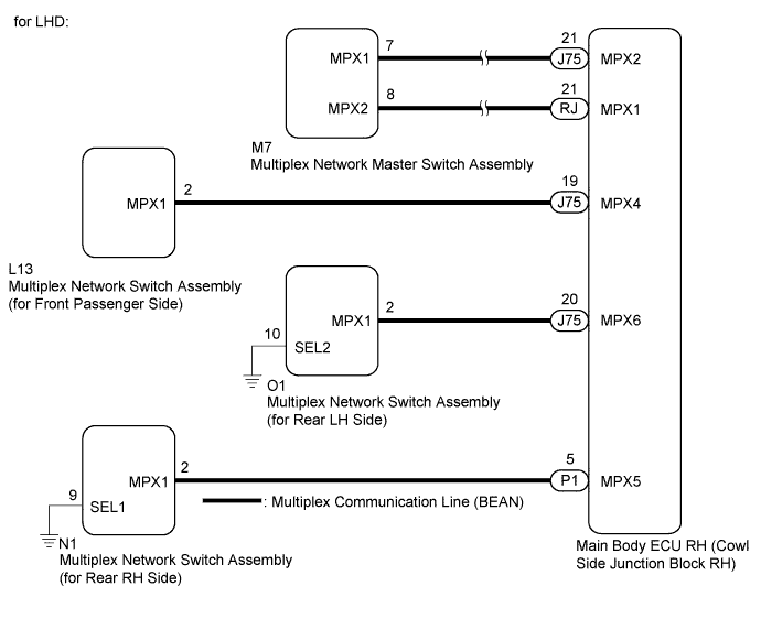
When the engine switch is on (IG) and the window lock switch is OFF, the multiplex network master switch assembly sends remote up / down signal to each multiplex network switch assembly via the multiplex communication line (BEAN).
WIRING DIAGRAM

INSPECTION PROCEDURE
Note
-
When the multiplex network master switch assembly connector or multiplex network switch assembly (applicable location) connector is disconnected, the power window control system must be initialized Click here.
-
Since the power window control system has functions that use multiplex communication, first confirm that there is no malfunction in the multiplex communication system by inspecting the multiplex communication functions in accordance with the How to Proceed with Troubleshooting procedures Click here. Then, conduct the following inspection procedure.
PROCEDURE
-
CHECK POWER WINDOW CONTROL SYSTEM (WINDOW LOCK SWITCH)
-
Check that the multiplex network switch assemblies (front passenger, rear LH and rear RH side) are disabled when the window lock switch of the multiplex network master switch assembly is pressed.
OK Multiplex network switch assemblies (front passenger, rear LH and rear RH side) are disabled. -
Check that the multiplex network switch assemblies (front passenger, rear LH and rear RH side) operate when the window lock switch is pressed again.
OK Multiplex network switch assemblies (front passenger, rear LH and rear RH side) can be operated.
NG 
READ VALUE USING INTELLIGENT TESTER (MASTER SWITCH) Click here
OK 
END
-
-
READ VALUE USING INTELLIGENT TESTER (MASTER SWITCH)
-
Connect the intelligent tester to the DLC3.
-
Turn the engine switch on (IG)
-
Turn the intelligent tester on.
-
Enter the following menus: Body / Master Switch / Data List.
-
Read the Data List according to the display on the intelligent tester.
Master Switch (Multiplex Network Master Switch Assembly) Tester Display Measurement Item/Range Normal Condition Diagnostic Note P Door P/W Auto SW Front passenger side power window auto up/down switch signal/ON or OFF ON: Front passenger side power window switch is operated (Auto operation)
OFF: Front passenger side power window switch is not operated
- Rl Door P/W Auto SW Rear LH power window auto up/down switch signal/ON or OFF ON: Rear LH power window switch is operated (Auto operation)
OFF: Rear LH power window switch is not operated
- Rr Door P/W Auto SW Rear RH power window auto up/down switch signal/ON or OFF ON: Rear RH power window switch is operated (Auto operation)
OFF: Rear RH power window switch is not operated
- P Door P/W Up SW Front passenger side power window manual up switch signal/ON or OFF ON: Front passenger side power window switch is operated (Manual up operation)
OFF: Front passenger side power window switch is not operated
- Rl Door P/W Up SW Rear LH power window manual up switch signal/ON or OFF ON: Rear LH power window switch is operated (Manual up operation)
OFF: Rear LH power window switch is not operated
- Rr Door P/W Up SW Rear RH power window manual up switch signal/ON or OFF ON: Rear RH power window switch is operated (Manual up operation)
OFF: Rear RH power window switch is not operated
- P Door P/W Down SW Front passenger side power window manual down switch signal/ON or OFF ON: Front passenger side power window switch is operated (Manual down operation)
OFF: Front passenger side power window switch is not operated
- Rl Door P/W Down SW Rear LH power window manual down switch signal/ON or OFF ON: Rear LH power window switch is operated (Manual down operation)
OFF: Rear LH power window switch is not operated
- Rr Door P/W Down SW Rear RH power window manual down switch signal/ON or OFF ON: Rear RH power window switch is operated (Manual down operation)
OFF: Rear RH power window switch is not operated
- Window Lock Switch Status Window lock switch signal/ON or OFF ON: Window lock switch LOCK position
OFF: Window lock switch UNLOCK position
- OK The intelligent tester display changes in accordance with multiplex network master switch assembly operation.
NG 
REPLACE MULTIPLE NETWORK MASTER SWITCH ASSEMBLY Click here
OK 
-
-
CHECK POWER WINDOW CONTROL SYSTEM (Remote Up/Down Function (Each Doors))
-
Check that the each door remote up/down function operates Click here.
Result Result Proceed to Front passenger side does not operate A Rear LH side does not operate B Rear RH side does not operate C All doors do not operate D
A
CHECK HARNESS AND CONNECTOR (MAIN BODY ECU RH - SWITCH (for Front Passenger Side)) Click here
B
CHECK HARNESS AND CONNECTOR (MAIN BODY ECU RH - SWITCH (for Rear LH Side)) Click here
C
CHECK HARNESS AND CONNECTOR (MAIN BODY ECU RH - SWITCH (for Rear RH Side)) Click here
D
-
-
CHECK DTC OUTPUT (MULTIPLEX COMMUNICATION SYSTEM)
-
Check the DTC Click here.
OK B1206 output does not recur.
NG
GO TO MULTIPLEX COMMUNICATION SYSTEM (DTC 1206) Click here
OK
REPLACE MULTIPLE NETWORK MASTER SWITCH ASSEMBLY Click here
-
-
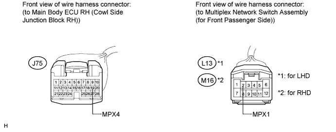
CHECK HARNESS AND CONNECTOR (MAIN BODY ECU RH - SWITCH (for Front Passenger Side))
-
Disconnect the main body ECU RH (cowl side junction block RH).
-
Disconnect the multiplex network switch assembly (for front passenger side).
-
Measure the resistance according to the value(s) in the table below.
Standard Resistance for LHD Tester Connection Condition Specified Condition J75-19 (MPX4) - L13-2 (MPX1) Always Below 1 Ω J75-19 (MPX4) - Body ground Always 10 kΩ or higher for RHD Tester Connection Condition Specified Condition J75-19 (MPX4) - M16-2 (MPX1) Always Below 1 Ω J75-19 (MPX4) - Body ground Always 10 kΩ or higher
NG
REPAIR OR REPLACE HARNESS OR CONNECTOR
OK
-
-
REPLACE MULTIPLEX NETWORK SWITCH ASSEMBLY (for Front Passenger Side)
-
Replace the multiplex network switch assembly (for front passenger side) Click here.
NEXT
-
-
PERFORM INITIALIZATION (POWER WINDOW CONTROL SYSTEM (for Front Passenger Side))
-
Initialize the power window control system (for front passenger side) Click here.
NEXT
-
-
CHECK POWER WINDOW CONTROL SYSTEM (Front Passenger Side Remote Up/Down Function)
-
Check that the front passenger side remote up/down function operates normally Click here.
OK Front passenger side remote up/down function operates normally.
NG
REPLACE MAIN BODY ECU RH (COWL SIDE JUNCTION BLOCK RH)
OK
END (MULTIPLEX NETWORK SWITCH ASSEMBLY IS DEFECTIVE)
-
-
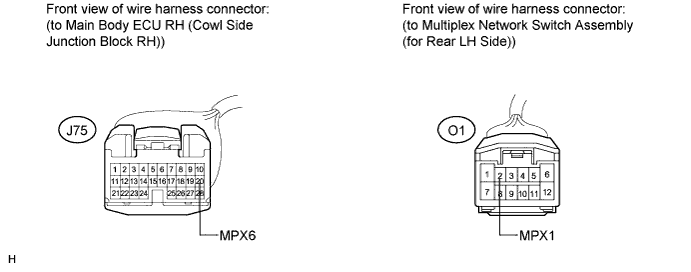
CHECK HARNESS AND CONNECTOR (MAIN BODY ECU RH - SWITCH (for Rear LH Side))
-
Disconnect the main body ECU RH (cowl side junction block RH).
-
Disconnect the multiplex network switch assembly (for rear LH side).
-
Measure the resistance according to the value(s) in the table below.
Standard Resistance Tester Connection Condition Specified Condition J75-20 (MPX6) - O1-2 (MPX1) Always Below 1 Ω J75-20 (MPX6) - Body ground Always 10 kΩ or higher
NG
REPAIR OR REPLACE HARNESS OR CONNECTOR
OK
-
-
REPLACE MULTIPLEX NETWORK SWITCH ASSEMBLY (for Rear LH Side)
-
Replace the multiplex network switch assembly (for rear LH side) Click here.
NEXT
-
-
PERFORM INITIALIZATION (POWER WINDOW CONTROL SYSTEM (for Rear LH Side))
-
Initialize the power window control system (for rear LH side) Click here.
NEXT
-
-
CHECK POWER WINDOW CONTROL SYSTEM (Rear LH Side Rremote Up/Down Function)
-
Check that the rear LH side remote up/down function operates normally Click here.
OK Rear LH side remote up/down function operates normally.
NG
REPLACE MAIN BODY ECU RH (COWL SIDE JUNCTION BLOCK RH)
OK
END (MULTIPLEX NETWORK SWITCH ASSEMBLY IS DEFECTIVE)
-
-
CHECK HARNESS AND CONNECTOR (MAIN BODY ECU RH - SWITCH (for Rear RH Side))
-
Disconnect the main body ECU RH (cowl side junction block RH).
-
Disconnect the multiplex network switch assembly (for rear RH side).
-
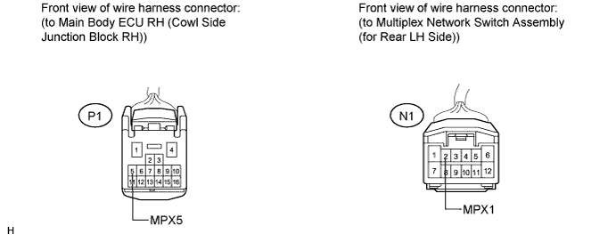
Measure the resistance according to the value(s) in the table below.
Standard Resistance Tester Connection Condition Specified Condition P1-5 (MPX5) - N1-2 (MPX1) Always Below 1 Ω P1-5 (MPX5) - Body ground Always 10 kΩ or higher
NG
REPAIR OR REPLACE HARNESS OR CONNECTOR
OK
-
-
REPLACE MULTIPLEX NETWORK SWITCH ASSEMBLY (for Rear RH Side)
-
Replace the multiplex network switch assembly (for rear RH side) Click here.
NEXT
-
-
PERFORM INITIALIZATION (POWER WINDOW CONTROL SYSTEM (for Rear RH Side))
-
Initialize the power window control system (for rear RH side) Click here.
NEXT
-
-
CHECK POWER WINDOW CONTROL SYSTEM (Rear RH Side Remote Up/Down Function)
-
Check that the rear RH side remote up/down function operates normally Click here.
OK Rear RH side remote up/down function operates normally.
NG
REPLACE MAIN BODY ECU RH (COWL SIDE JUNCTION BLOCK RH)
OK
END (MULTIPLEX NETWORK SWITCH ASSEMBLY IS DEFECTIVE)
-