INSTRUMENT PANEL SAFETY PAD DISASSEMBLY

-
REMOVE NO. 1 HEATER TO REGISTER DUCT
-
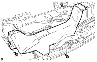
Remove the 3 screws <E> and the No. 1 heater to register duct.
-
-
REMOVE NO. 3 HEATER TO REGISTER DUCT
-
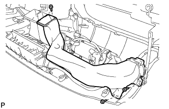
Remove the 3 screws <E> and the No. 3 heater to register duct.
-
-
REMOVE SIDE NO. 1 DEFROSTER NOZZLE DUCT
-
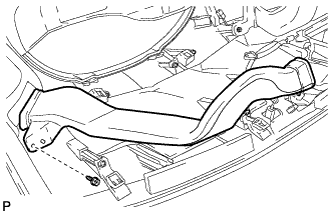
Remove the screw <E> and the side No. 1 defroster nozzle duct.
-
-
REMOVE SIDE NO. 2 DEFROSTER NOZZLE DUCT
-
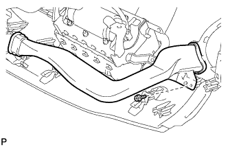
Remove the screw <E> and the side No. 2 defroster nozzle duct.
-
-
REMOVE DEFROSTER NOZZLE ASSEMBLY
-
Remove the 3 screws <E> and the defroster nozzle assembly.
-
-
REMOVE NO. 2 HEATER TO REGISTER DUCT
-
Remove the 4 screws <E> and the No. 2 heater to register duct.
-
-
REMOVE SIDE DEFROSTER NOZZLE
-
Disengage the 4 claws and remove the side defroster nozzle.
-
-
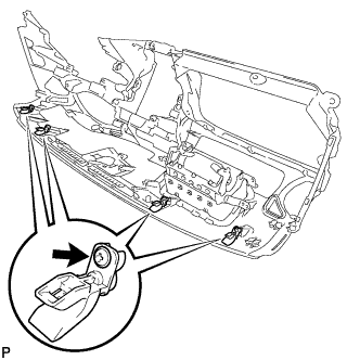
REMOVE NO. 2 ANTENNA CORD SUB-ASSEMBLY
-
Disengage the clamp and remove the No. 2 antenna cord sub-assembly.
-
-
REMOVE NAVIGATION ANTENNA ASSEMBLY
-
Disengage the 2 clamps.
-
Remove the 2 screws and navigation antenna.
-
-
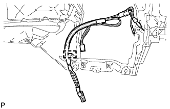
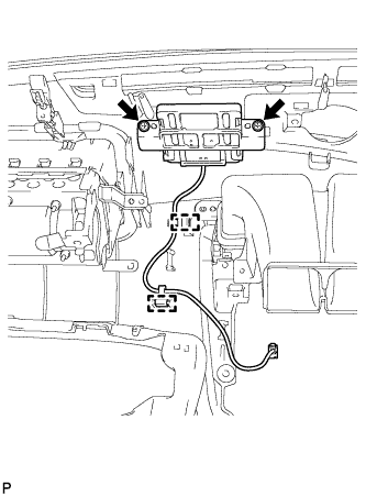
REMOVE NO. 2 INSTRUMENT PANEL WIRE
-
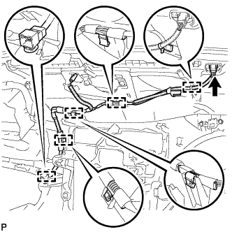
Disconnect the connector.
-
Disengage the 5 clamps and remove the No. 2 instrument panel wire.
-
-
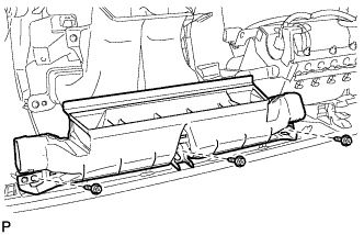
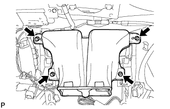
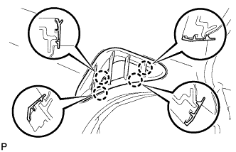
REMOVE FRONT PASSENGER AIRBAG ASSEMBLY
-
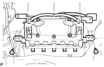
Remove the 2 screws.
-
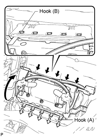
Disengage the 5 hooks (A).
-
Disengage the 5 hooks (B) and remove the front passenger airbag assembly from the instrument panel safety pad assembly as shown in the illustration.
-
-
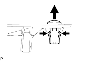
REMOVE DEFROSTER NOZZLE GARNISH
-
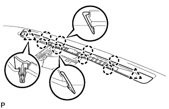
Disengage the 8 claws and 2 clips, and then remove the defroster nozzle garnish.
-
-
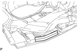
REMOVE AUTOMATIC LIGHT CONTROL SENSOR
-
Disengage the 2 claws and remove the automatic light control sensor.
-
-
REMOVE ENGINE SWITCH
-
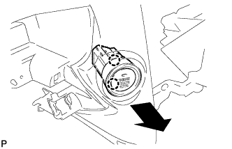
Disengage the 2 claws and remove the engine switch.
-
-
REMOVE INSTRUMENT PANEL SPACER
-
Remove the instrument panel spacer.
-
-
REMOVE NO. 1 INSTRUMENT PANEL PIN
-
Remove the 4 screws <E> and the 4 No. 1 instrument panel pins.
-