COMPRESSOR REMOVAL

-
DISCHARGE REFRIGERANT FROM REFRIGERATION SYSTEM
-
Start up the engine.
-
Turn the A/C switch on.
-
Operate the cooler compressor at an engine speed of approximately 1000 rpm for 5 to 6 minutes to circulate the refrigerant and collect the compressor oil remaining in each component into the cooler compressor.
-
Stop the engine.
-
Recover the refrigerant from the A/C system using a refrigerant recovery unit.
-
-
REMOVE COOL AIR INTAKE DUCT SEAL
-
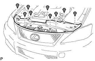
Using a clip remover, remove the 9 clips and cool air intake duct seal.
-
-
REMOVE NO. 1 AIR CLEANER INLET
-
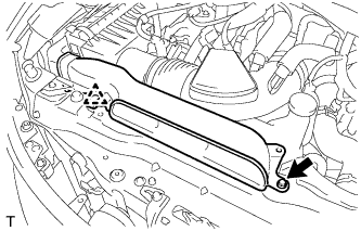
Remove the bolt, clip and No. 1 air cleaner inlet.
-
-
SEPARATE RADIATOR RESERVE TANK ASSEMBLY
-
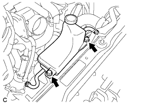
Remove the 2 bolts and separate the radiator reserve tank assembly.
-
-
REMOVE V-RIBBED BELT
-
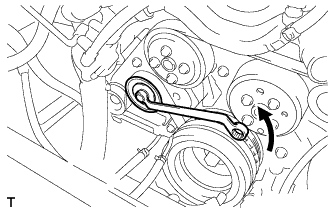
Rotate the V-ribbed belt tensioner pulley counterclockwise to loosen the V-ribbed belt tensioner.
Tech Tips
The pulley bolt for the V-ribbed belt tensioner is reverse threaded.
-
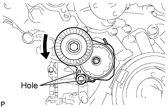
While turning the V-ribbed belt tensioner counterclockwise, align the holes. Insert a bar of φ5 mm (0.197 in.) into the holes to secure the V-ribbed belt tensioner in place.
-
Remove the V-ribbed belt.
-
-
REMOVE ENGINE UNDER COVER
-
REMOVE REAR ENGINE UNDER COVER LH
-
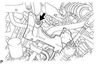
Remove the bolt and engine under cover LH.
-
-
DISCONNECT NO. 1 COOLER REFRIGERANT SUCTION HOSE
-
Disconnect the connector.
-
Disengage each clamp.
-
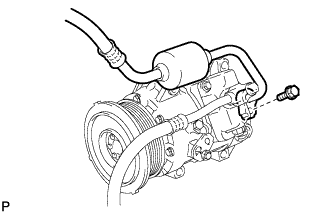
Remove the bolt and disconnect the No. 1 cooler refrigerant suction hose from the compressor.
-
Remove the O-ring from the cooler refrigerant suction hose.
Note
Seal the openings of the disconnected parts using vinyl tape to prevent moisture and foreign matter from entering.
-
-
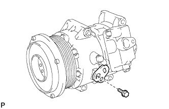
DISCONNECT DISCHARGE HOSE SUB-ASSEMBLY
-
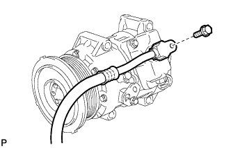
Remove the bolt and disconnect the discharge sub-assembly from the compressor.
-
Remove the O-ring from the discharge sub-assembly.
Note
Seal the openings of the disconnected parts using vinyl tape to prevent moisture and foreign matter from entering.
-
-
REMOVE COMPRESSOR AND PULLEY
-
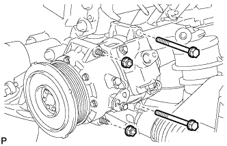
Remove the 2 bolts and 2 nuts.
-
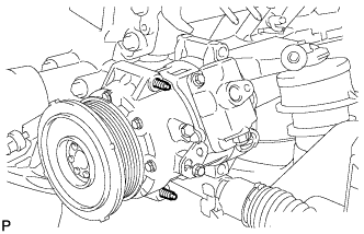
Using an E8 "TORX" socket, remove the 2 stud bolts and compressor.
Tech Tips
Remove the compressor and pulley from the vehicle with the stud bolts remaining in the compressor.
-
Remove the bolt and bracket.
-