AIR CONDITIONING UNIT REMOVAL

-
DISCHARGE REFRIGERANT FROM REFRIGERATION SYSTEM
-
Start up the engine.
-
Turn the A/C switch on.
-
Operate the cooler compressor at an engine speed of approximately 1000 rpm for 5 to 6 minutes to circulate the refrigerant and collect the compressor oil remaining in each component into the cooler compressor.
-
Stop the engine.
-
Recover the refrigerant from the A/C system using a refrigerant recovery unit.
-
-
REMOVE WINDSHIELD WIPER MOTOR AND LINK ASSEMBLY
-
SEPARATE SUCTION PIPE SUB-ASSEMBLY
-
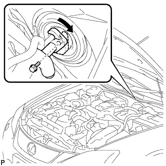
Remove the bolt, and slide the hook connector.
-
Disconnect the suction pipe sub-assembly.
-
Remove the O-ring from the suction pipe sub-assembly.
Note
Seal the openings of the disconnected parts using vinyl tape to prevent moisture and foreign matter from entering.
-
-
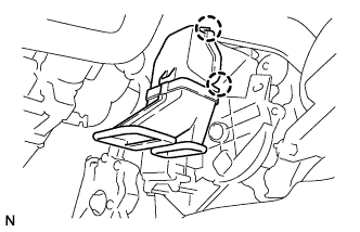
SEPARATE COOLER REFRIGERANT LIQUID PIPE A
-
Disconnect the cooler refrigerant liquid pipe A.
-
Remove the O-ring from the cooler refrigerant liquid pipe A.
Note
Seal the openings of the disconnected parts using vinyl tape to prevent moisture and foreign matter from entering.
-
-
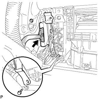
REMOVE HEATER WATER OUTLET HOSE
-

Using pliers, grip the claws of the clip and slide the clip to disconnect the heater water outlet hose.
-
-
REMOVE HEATER WATER INLET HOSE
Tech Tips
Use the same procedure for the heater water outlet hose.
-
REMOVE INSTRUMENT PANEL SAFETY PAD ASSEMBLY
-
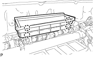
REMOVE NO. 1 AIR DUCT
-
Disengage the 2 claws and remove the No. 1 air duct.
-
-
REMOVE STEERING COLUMN ASSEMBLY
-
REMOVE LOWER DEFROSTER NOZZLE ASSEMBLY
-
Release the 4 claws and remove the lower defroster nozzle assembly.
-
-
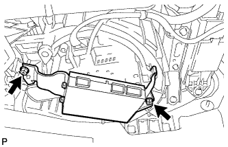
REMOVE POWER SOURCE CONTROL ECU WITH BRACKET (for RHD)
-
Disconnect the connector.
-
Remove the bolt and nut, and the power source control ECU with bracket.
-
-
REMOVE MULTI-MEDIA INTERFACE ECU WITH BRACKET (for LHD)
-
Disconnect each connector.
-
Remove the 2 screws and multi-media interface ECU with bracket.
-
-
REMOVE SKID CONTROL BUZZER
-
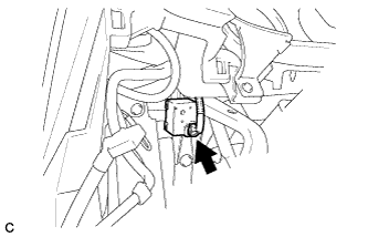
Disconnect the skid control buzzer connector.
-
Remove the clip and skid control buzzer.
-
-
REMOVE PARKING ASSIST ECU (w/ Parking Assist Monitor System)
for LHD: Click here
for RHD: Click here
-
REMOVE DISTANCE CONTROL ECU (w/ Dynamic Radar Cruise Control System)
for LHD: Click here
for RHD: Click here
-
REMOVE CLEARANCE WARNING BUZZER (w/ LEXUS Parking Assist-sensor System)
for LHD: Click here
for RHD: Click here
-
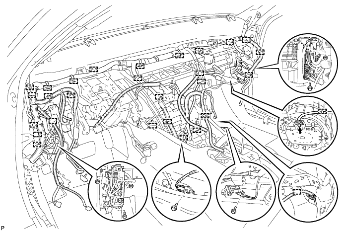
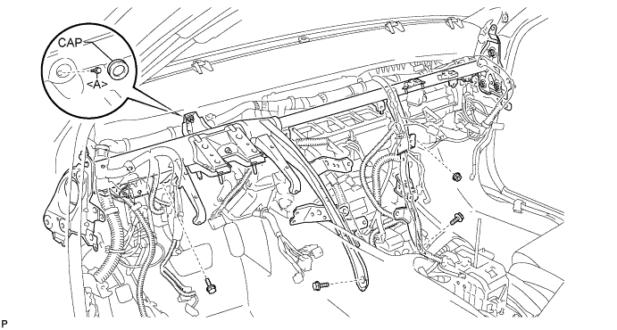
REMOVE INSTRUMENT PANEL REINFORCEMENT ASSEMBLY
-
Disengage each clamp and disconnect each connector.
-
Remove the 2 bolts and 2 earth wires.
-
Remove the 3 nuts, 2 bolts and 2 junction blocks.
-
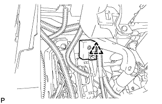
Remove the cap and bolt <A>.
-
Remove the 3 bolts and nut.
-
Remove the 6 caps.
-
Remove the 2 bolts.
-
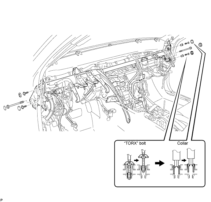
Using a T40 "TORX" socket, remove the 4 "TORX" bolts.
Note
The "TORX" bolts on the passenger side can be removed with the collar for adjustment.
-
Using a 12 mm hexagon wrench, remove the 2 collars and instrument panel reinforcement.
-
-
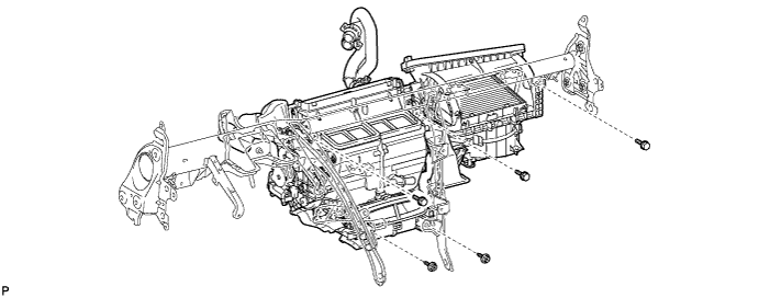
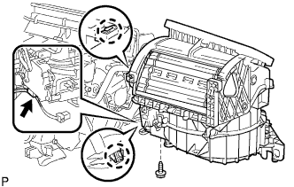
REMOVE AIR CONDITIONER UNIT ASSEMBLY
-
Remove the 2 screws, 3 bolts, and air conditioner unit assembly.
-
Using pliers, grip the claws of the clip and slide the clip to remove the heater water outlet hose.
-
Using pliers, grip the claws of the clip and slide the clip to remove the heater water inlet hose.
-
-
REMOVE NO. 2 AIR DUCT
-
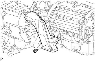
Remove the screw and No. 2 air duct.
-
-
REMOVE AIR CONDITIONING AMPLIFIER ASSEMBLY
-

Disconnect the connector.
-
Remove the screw and air conditioning amplifier assembly.
-
-
REMOVE BLOWER ASSEMBLY
-
Disconnect the connector.
-
Remove the screw.
-
Release the claw and remove the blower assembly.
-