CONDENSER REMOVAL

-
REMOVE COOL AIR INTAKE DUCT SEAL
-
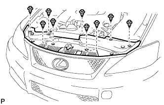
Using a clip remover, remove the 9 clips and cool air intake duct seal.
-
-
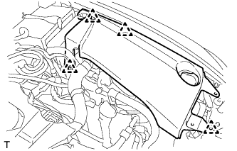
REMOVE ENGINE ROOM SIDE COVER LH (for LHD)
-

Remove the 5 clips and engine room side cover LH.
-
-
REMOVE ENGINE ROOM SIDE COVER LH (for RHD)
-
Remove the 4 clips and engine room side cover LH.
-
-
REMOVE ENGINE ROOM SIDE COVER RH (for LHD)
-
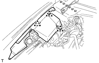
Remove the 3 clips and engine room side cover RH.
-
-
REMOVE ENGINE ROOM SIDE COVER RH (for RHD)
-
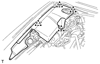
Remove the 4 clips and engine room side cover RH.
-
-
REMOVE V-BANK COVER SUB-ASSEMBLY
-
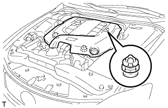
Hold the front of the V-bank cover sub-assembly and raise it to disengage the 2 clips on the front of the cover. Continue to raise the cover to disengage the 2 clips on the rear of the cover and remove the V-bank cover sub-assembly.
Note
Attempting to disengage both front and rear clips at the same time may cause the cover to break.
-
-
DISCHARGE REFRIGERANT FROM REFRIGERATION SYSTEM
-
Start up the engine.
-
Turn the A/C switch on.
-
Operate the cooler compressor at an engine speed of approximately 1000 rpm for 5 to 6 minutes to circulate the refrigerant and collect the compressor oil remaining in each component into the cooler compressor.
-
Stop the engine.
-
Recover the refrigerant from the A/C system using a refrigerant recovery unit.
-
-
REMOVE NO. 1 AIR CLEANER INLET
-
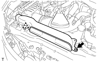
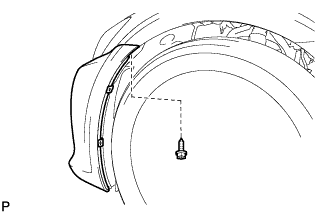
Remove the bolt, clip and No. 1 air cleaner inlet.
-
-
REMOVE RADIATOR GRILLE PROTECTOR
-
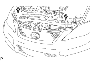
Remove the 2 radiator grille protectors.
-
-
REMOVE FRONT BUMPER ASSEMBLY
-
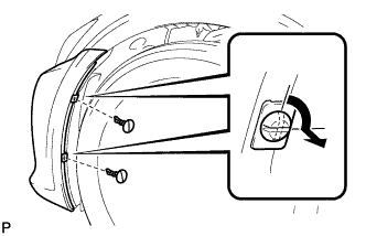
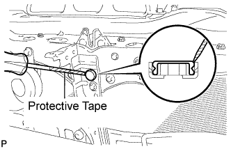
Using a screwdriver, turn the pins 90 degrees and remove the 2 pin hold clips.
Tech Tips
-
Tape the screwdriver tip before use.
-
Use the same procedure for the RH side and LH side.
-
-
remove the screw.
Tech Tips
Use the same procedure for the RH side and LH side.
-
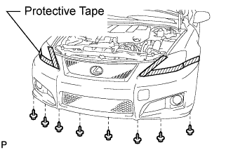
Put protective tape around the front bumper assembly.
-
Remove the 8 screws.
-
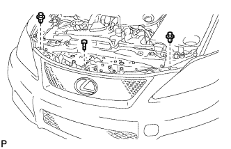
Using a clip remover, remove the 2 clips and screw.
-
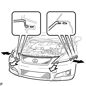
Disengage the 10 claws and disconnect the front bumper assembly as shown in the illustration.
-
w/ LEXUS Parking Assist-Sensor system:
-
Disconnect the ultrasonic sensor connector.
-
-
Disconnect the headlight cleaner hose.
Note
Prepare a drain pan or a piece of cloth in case washer fluid leaks.
-
Disconnect the 2 fog light connectors and remove the front bumper assembly.
-
-
REMOVE FRONT BUMPER ENERGY ABSORBER
-
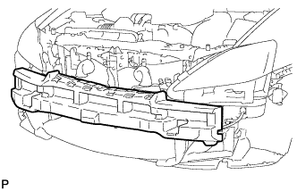
Remove the front bumper energy absorber.
-
-
REMOVE RADIATOR SUPPORT OPENING COVER
-
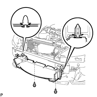
Remove the 2 screws.
-
Disengage the 4 clips and the radiator support opening cover.
-
-
REMOVE MILLIMETER WAVE RADAR SENSOR ASSEMBLY (w/ Dynamic Radar Cruise Control System)
-
Disconnect the connector.
-
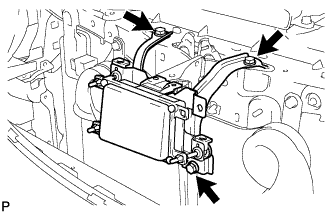
Remove the 3 bolts and the millimeter wave radar sensor assembly.
-
-
REMOVE HOOD LOCK CONTROL CABLE COVER
-
Remove the 3 screws.
-
Disengage the clamp and remove the hood lock control cable cover.
-
-
REMOVE HOOD LOCK NUT CAP
-
Using a screwdriver, remove the hood lock nut cap as shown in the illustration.
Tech Tips
Tape the screwdriver tip before use.
-
-
REMOVE HOOD LOCK ASSEMBLY
-
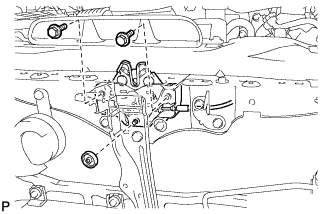
Remove the 2 bolts and hood lock nut.
-
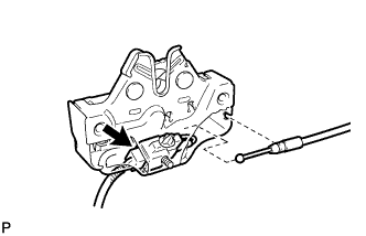
Disconnect the hood lock control cable assembly.
-
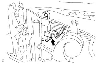
Disconnect the connector and remove the hood lock assembly.
-
-
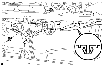
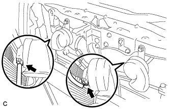
REMOVE UPPER RADIATOR SUPPORT
-
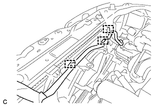
Disconnect the smog ventilation sensor connector.
-
Disconnect the 2 horn connectors.
-
Separate the 5 clamps and the wire harness from the upper radiator support.
-
Separate the 2 clamps and the wire harness from the upper radiator support.
-
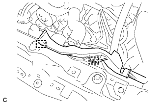
Separate the 3 clamps and the wire harness from the fan shroud.
-
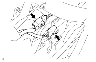
Disconnect the 2 cooling fan ECU connectors.
-
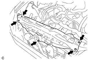
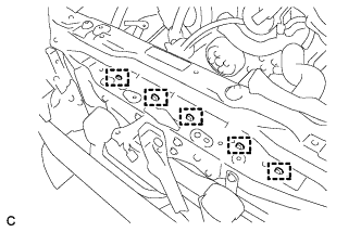
Remove the 5 bolts and the upper radiator support.
-
-
DISCONNECT OIL COOLER BRACKET
-
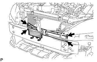
Remove the 4 bolts and disconnect the oil cooler bracket from the cooler condenser assembly.
-
-
DISCONNECT LIQUID PIPE SUB-ASSEMBLY
-
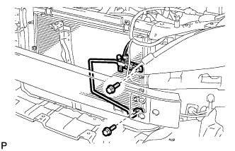
Remove the 2 bolts and disconnect the liquid pipe sub-assembly from the cooler condenser assembly.
-
Remove the O-ring from the liquid pipe sub-assembly.
Note
Seal the openings of the disconnected parts using vinyl tape to prevent moisture and foreign matter from entering.
-
-
DISCONNECT NO. 1 COOLER REFRIGERANT DISCHARGE HOSE
-
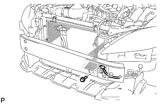
Remove the bolt and disconnect the No. 1 cooler refrigerant discharge hose from the cooler condenser assembly.
-
Remove the O-ring from the No. 1 cooler refrigerant discharge hose.
Note
Seal the openings of the disconnected parts using vinyl tape to prevent moisture and foreign matter from entering.
-
-
REMOVE COOLER CONDENSER ASSEMBLY
-
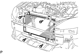
Remove the 4 bolts and cooler condenser assembly.
-
-
REMOVE COOLER DRYER
-
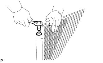
Using a 14 mm straight hexagon wrench, remove the cap from the modulator.
-
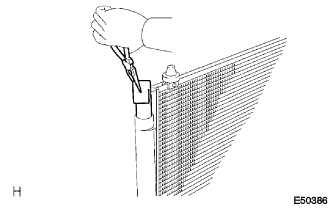
Using pliers, remove the cooler dryer.
-