COMPRESSOR INSTALLATION

-
ADJUST COMPRESSOR OIL
-
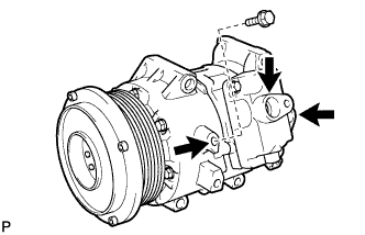
When replacing the cooler compressor assembly with a new one, gradually discharge the inert gas (helium) from the service valve, and drain the following amount of oil from the vents indicated by the arrows in the illustration before installation.
Tech Tips
The drain bolt and washer can be reused.
Standard (Oil capacity inside a new compressor and pulley: 130 + 15 cc (4.6 + 0.51 fl.oz.)) - (Remaining oil amount in the removed compressor and pulley) = (Oil amount to be removed when replacing the compressor) Note
-
If a new compressor is installed without removing some oil, due to the oil remaining in the pipes of the vehicle, the oil amount will be too large. This prevents heat exchange in the refrigerant cycle and causes refrigeration system failure.
-
If the volume of oil remaining in the removed compressor is too small, check for oil leakage.
-
Be sure to use ND-OIL 8 or equivalent for compressor oil.
-
-
-
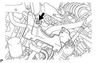
INSTALL COMPRESSOR AND PULLEY
-
Install the bracket with the bolt.
-
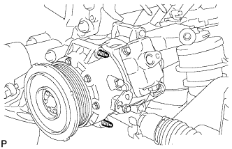
Using an E8 "TORX" socket, install the compressor and pulley with the 2 stud bolts.
- Torque:
- 10 N*m { 102 kgf*cm, 7 ft.*lbf }
-
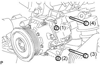
Install the compressor and pulley with the 2 bolts and 2 nuts.
- Torque:
- 25 N*m { 255 kgf*cm, 18 ft.*lbf }
Tech Tips
Tighten the bolts in the order shown in the illustration to install the compressor.
-
-
INSTALL DISCHARGE HOSE SUB-ASSEMBLY
-
Remove the vinyl tape attached to the hose.
-
Apply sufficient compressor oil to a new O-ring and the fitting surface of the compressor and pulley.
Compressor oil ND-OIL 8 or equivalent -
Install the O-ring onto the discharge hose sub-assembly.
-
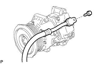
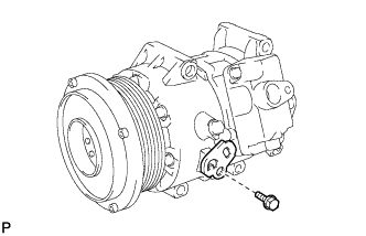
Install the discharge hose sub-assembly onto the compressor and pulley with the bolt.
- Torque:
- 9.8 N*m { 100 kgf*cm, 87 in.*lbf }
-
-
INSTALL NO. 1 COOLER REFRIGERANT SUCTION HOSE
-
Remove the vinyl tape attached to the hose.
-
Apply sufficient compressor oil to a new O-ring and the fitting surface of the compressor and pulley.
Compressor oil ND-OIL 8 or equivalent -
Install the O-ring onto the No. 1 cooler refrigerant suction hose.
-
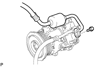
Install the No. 1 cooler refrigerant suction hose onto the compressor and pulley with the bolt.
- Torque:
- 9.8 N*m { 100 kgf*cm, 87 in.*lbf }
-
Engage each clamp.
-
Connect the connector.
-
-
INSTALL REAR ENGINE UNDER COVER LH
-
Install the engine under cover LH with the bolt.
-
-
INSTALL ENGINE UNDER COVER
-
INSTALL V-RIBBED BELT
-
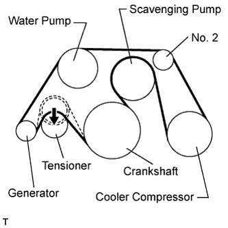
Install the V-ribbed belt as shown in the illustration.
-
Rotate the V-ribbed belt tensioner pulley counterclockwise, and then remove the bar.
Note
Check that the drive belt is properly set to each pulley.
-
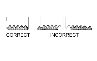
Check that the belt is properly positioned on each pulley.
-
Start the engine and check that the belt turns smoothly and no abnormal noise occurs.
-
-
INSTALL RADIATOR RESERVE TANK ASSEMBLY
-
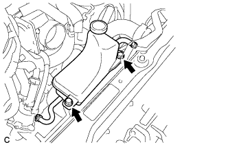
Install the radiator reserve tank assembly with the 2 bolts.
- Torque:
- 5.0 N*m { 51 kgf*cm, 44 in.*lbf }
-
-
INSTALL NO. 1 AIR CLEANER INLET
-
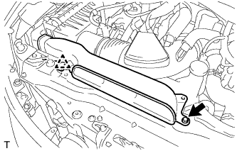
Install the No. 1 air cleaner inlet with the bolt and clip.
- Torque:
- 5.0 N*m { 51 kgf*cm, 44 in.*lbf }
-
-
INSTALL COOL AIR INTAKE DUCT SEAL
-
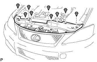
Install the cool air intake duct seal with the 9 clips.
-
-
CHARGE REFRIGERANT
-
Perform vacuum purging using a vacuum pump.
-
Charge refrigerant HFC-134a (R134a).
Standard 400 to 500g (14.10 to 17.63 oz.) - SST
- 09985-20010 ( 09985-02010, 09985-02050, 09985-02060, 09985-02070, 09985-02080, 09985-02090, 09985-02110, 09985-02130, 09985-02140, 09985-02150 )
Note
-
Do not operate the cooler compressor before charging refrigerant as the cooler compressor will not work properly without any refrigerant, and will overheat.
-
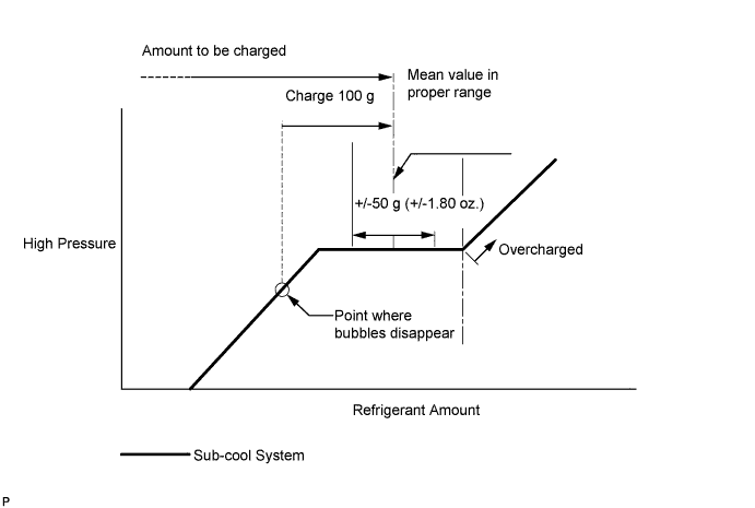
Approximately 100 g (3.53 oz.) of refrigerant may need to be charged after bubbles disappear. The refrigerant amount should be checked by measuring its quantity, and not with the sight glass.
-
-
WARM UP ENGINE
-
Warm up the engine at less than 1570 rpm for 2 minutes or more after charging the refrigerant.
Note
Be sure to warm up the compressor when turning the A/C switch ON after removing and installing the cooler refrigerant lines (including the compressor), to prevent damage to the compressor.
-
-
INSPECT FOR REFRIGERANT LEAK
-
After recharging the refrigerant gas, check for refrigerant gas leakage using a halogen leak detector.
-
Perform the operation under the following conditions:
-
Stop the engine.
-
Secure good ventilation (the gas leak detector may react to volatile gases other than refrigerant, such as evaporated gasoline or exhaust gas).
-
Repeat the test 2 or 3 times.
-
Make sure that some refrigerant remains in the refrigeration system. When compressor is off: approximately 392 to 588 kPa (4 to 6 kgf/cm2, 57 to 85 psi)
-
-
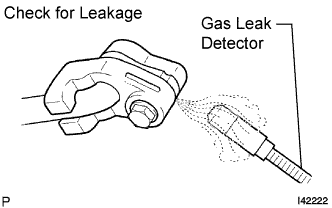
Using a gas leak detector, check the refrigerant line for leakage.
-
If a gas leak is not detected on the drain hose, remove the blower motor control (blower resistor) from the cooling unit. Insert the gas leak detector sensor into the unit and perform the test.
-
Disconnect the connector and leave the pressure switch on for approximately 20 minutes. Bring the gas leak detector close to the pressure switch and perform the test.
-