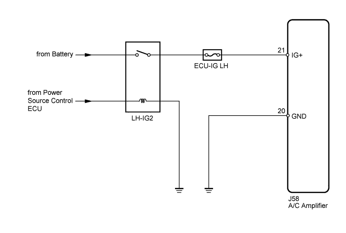
AIR CONDITIONING SYSTEM IG Power Source Circuit
DESCRIPTION
The main power source is supplied to the A/C amplifier when the engine switch on (IG).
The power source is used for operating the A/C amplifier and servo motor, etc.
WIRING DIAGRAM
INSPECTION PROCEDURE
Tech Tips
Start the engine before inspection. Check the IG1 relay or battery if the engine does not start.
PROCEDURE
-
INSPECT FUSE (ECU-IG LH)
-
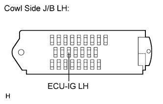
Remove the ECU-IG LH fuse from the cowl side junction block LH.
-
Measure the resistance according to the value(s) in the table below.
Standard Resistance Tester Item Condition Specified Condition ECU-IG LH fuse Always Below 1 Ω
NG 
REPLACE FUSE (ECU-IG LH)
OK 
-
-
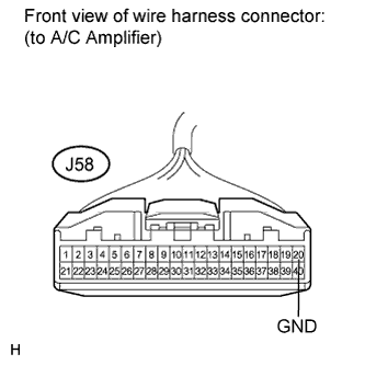
INSPECT A/C AMPLIFIER (IG+ - GND)
-
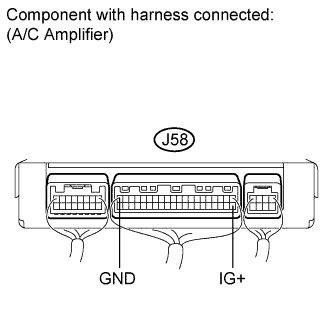
Remove the A/C amplifier with its connectors still connected.
-
Turn the engine switch on (IG).
-
Measure the voltage according to the value(s) in the table below.
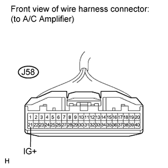
Standard Voltage Tester Connection Switch Condition Specified Condition J58-21 (IG+) - J58-20 (GND) Engine switch on (IG) 11 to 14 V
NG 
CHECK HARNESS AND CONNECTOR (A/C AMPLIFIER - BATTERY) Click here
OK 
PROCEED TO NEXT CIRCUIT INSPECTION SHOWN IN PROBLEM SYMPTOMS TABLE Click here
-
-
CHECK HARNESS AND CONNECTOR (A/C AMPLIFIER - BATTERY)
-
Disconnect the A/C amplifier connector.
-
Measure the voltage according to the value(s) in the table below.
Standard Voltage Tester Connection Switch Condition Specified Condition J58-21 (IG+) - Body ground Engine switch off Below 1 V Engine switch on (IG) 11 to 14 V
NG
REPAIR OR REPLACE HARNESS OR CONNECTOR
OK
-
-
CHECK HARNESS AND CONNECTOR (A/C AMPLIFIER - BODY GROUND)
-
Measure the resistance according to the value(s) in the table below.
Standard Resistance Tester Connection Condition Specified Condition J58-20 (GND) - Body ground Always Below 1 Ω
NG
REPAIR OR REPLACE HARNESS OR CONNECTOR
OK
REPLACE A/C AMPLIFIER Click here
-